Motors used in hazardous locations or severe-duty applications must meet a variety of stringent and sometimes unique requirements. An awareness and understanding of these requirements are critical to maintaining a productive and safe operating environment.
This article provides information to assist end-users in the application and maintenance of the appropriate motor for hazardous locations or severe-duty applications. It also provides checklists for new installations and preventive maintenance of hazardous-location and severe-duty motors.
Understanding classes and groups
Hazardous locations are environments in which explosive or ignitable vapors or dusts are present or might be present. Motors for such environments must be designed in a way that prevents external motor temperatures from igniting the vapor or dust and that contains any internal motor failures within the motor enclosure under all operating conditions.
To select the proper motor for a hazardous location, end-users must understand both the Underwriters Laboratories (UL) listed mark and the National Electrical Code (NEC) class, group and division designations and operating temperature codes.
Two primary classifications for hazardous location motors are available ," Class I and Class II. Each class has several subcategories called "groups."
A Class I motor is designed to withstand and confine the effects of an internal motor explosion, as well as to meet surface temperature requirements under all normal operating and fault conditions. Group letters A through D belong to Class I and designate different atmospheres in which the motor operates. Group A covers motors that operate in the most combustible atmospheres (acetylene), followed by Groups B, C and D. Table 1 describes the environments covered by each class.

A Class II motor covers dust in amounts sufficient to create explosive atmospheres, as well as dusts that are electrically conductive. A Class II motor is designed to prevent dust from entering the motor, while keeping the motor's surface temperature under the ignition temperature for the particular atmosphere during operation or fault condition. Group G (grain dust) has the lowest external surface temperature (165 Degrees C); Group E (metal dust) and Group F (carbon dust) have external surface temperatures of 200 Degrees C. The lowest ignition temperature of any material within the group determines the surface temperature limit for each group.
Not all Class I units are suitable for a Class II operation, and not all Class II units are suitable for a Class I operation. Very few manufacturers produce hazardous-location motors suitable for Class I, Groups A and B atmospheres.
Hazardous locations are further broken down into Division 1 and Division 2. A Division 1 location is one in which ignitable substances are likely to be present continuously or intermittently during normal operations. In a Division 2 location, ignitable materials are handled or stored in a way that could allow them to escape in the event of a spill or equipment failure.
Division designations do not appear on the UL label for Class I and Class II hazard location motors. All Class I and Class II motors are designed to meet Division 1 requirements and, therefore, are suitable for both Division 1 and Division 2 locations.
When a hazardous location motor is equipped with thermostats, the maximum temperature limit will not be exceeded both during operation and after the motor has been taken off-line.
All hazardous location motors manufactured after February 1975 must carry a temperature code that identifies the maximum motor surface temperature that could develop under all operating conditions ," everything from overload to motor burnout.

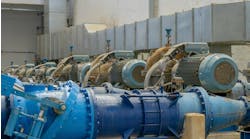
The photo shows a typical severe-duty motor application in a petrochemical plant.
(Photograph by EASA.)
Repairing hazardous-location motors
UL permits the repair of hazardous-location motors, but sets specific requirements. UL also inspects the repair facility to ensure compliance. Always make sure the repair facility has the proper UL approvals to repair these motors.
To retain UL certification, a repaired motor also must meet a number of requirements. First, it must have been listed by UL when it was originally manufactured. Second, it can be rebuilt and listed ONLY for the class and group for which it was originally designed.
Internal temperature protection (thermostat) is required for every rebuilt hazardous location motor. No modifications are permitted that could change the motor's temperature rise or ability to contain an internal explosion. UL does allow a voltage change as long as the original winding data are available.
For motors used with variable-frequency drives, it is especially important to obtain from the manufacturer the operating speed range for which the motor will still meet the temperature requirements of the listing. A motor that was not originally listed for inverter duty cannot be used on variable-frequency power unless the manufacturer has tested the design and determined that motor skin temperature will not exceed the required maximum throughout the frequency range for the application. For non-sinewave power, it is assumed that the motor will run 20 Degrees C hotter than it would on sinewave power.
Maintaining hazardous-location motors
Maintenance of hazardous location motors is essentially the same as for totally enclosed fan-cooled (TEFC) motors. Normally, maintenance includes lubrication at prescribed intervals; inspection for damage or evidence of corrosion, dirt and other debris accumulation on the frame and fan cover; and a check of vibration levels. If the motor is equipped with a thermostat, the thermostat circuit integrity also should be checked periodically.
Severe-duty motors
Two widely accepted petroleum and chemical industry standards are available for severe-duty application motors ," American Petroleum Institute (API) 541, Form-Wound Squirrel Cage Induction Motors-250 Horsepower and Larger, and Institute of Electrical and Electronics Engineers Inc. (IEEE) 841, IEEE Standard for Petroleum and Chemical Industry-Severe Duty Totally Enclosed Fan-Cooled (TEFC) Squirrel-Cage Induction Motors,"up to and Including 370 kW (500 hp).
A key difference between the standards is that API 541 deals with sleeve-bearing motors, whereas IEEE 841 applies to ball-bearing motors. The focus here is on horizontal IEEE 841 severe-duty motors. Table 2 identifies key features and benefits that distinguish these motors from standard TEFC motors.

A number of features set the IEEE 841 severe-duty motor apart from standard TEFC motors. Among them are corrosion-resistant coatings, stainless steel nameplates, seals to prevent water spray from entering the bearing chamber, cast-iron terminal boxes for ratings up to 600 volts (V) and oversized terminal boxes.
The enhanced corrosion resistance of the exterior substantially increases the time between recoatings. Shaft seals can withstand water projected from a nozzle, thereby extending bearing and, possibly, winding life, while reducing maintenance and repair requirements. Cast-iron terminal boxes provide durability in severe-duty applications.
Motors rated above 600 V could have terminal boxes fabricated from cast iron, cast steel or thick steel plate. The terminal box volume is at least twice that required for standard motors. Corrosion protection of the terminal box virtually eliminates maintenance.


Built-in benefits
The electrical design of severe-duty motors is geared for reliability, employing techniques that extend winding thermal life, voltage endurance and contamination resistance. The insulation system is at least Class F (155 Degrees C), and a contamination- and moisture-resistant sealed system vacuum-pressure impregnation winding is required for most form-coil windings.
Thermal life is enhanced by a winding temperature rise limit of 80 Degrees C, considerably lower than the 115 Degrees C rise for standard Class F TEFC motors. The increased thermal reserve of the winding improves reliability, even at the higher temperatures associated with operation on nonsinusoidal sources such as variable-frequency drives. Winding design features that provide greater resistance to contamination and moisture also increase voltage endurance, primarily by reducing or eliminating voids in the insulation system. Lower winding temperatures also mean less reflected heat to the bearings and a lower bearing temperature.
The standard TEFC motor protects against the ingress of small solid objects and the harmful effects of water splashed against it from any direction. In comparison, the protection afforded severe-duty motors prevents dust from entering in sufficient quantity to interfere with satisfactory motor operation. It also protects the bearings from the harmful effects of water projected in any direction by a nozzle. The replaceable shaft seals that often are used to fulfill this requirement are noncontact or noncontacting-while-rotating types, with a minimum expected life of five years under normal conditions. This degree of protection enhances reliability and reduces maintenance requirements.
Dynamic balance levels are about half those of standard TEFC motors, providing smoother operation and longer bearing life. Bearing temperature limits are likewise reduced to extend bearing and lubricant life. Shaft runout limits are about half those of NEMA-standard motors. Extended bearing life equates to less-frequent bearing change maintenance tasks and reduced downtime.
Corrosion protection extends beyond the frame of a severe-duty motor. Exposed interior parts of the stator, rotor and shaft must have a corrosion-resistant coating, with the rotor typically epoxy coated.
For durability, the frames, end brackets and fan covers of severe-duty motors must be of cast-iron construction. All unplated threaded surfaces are lubricated to facilitate removal. The joints between stator and end brackets are coated with a corrosion-resistant compound such as silicone rubber. These last two features facilitate disassembly when maintenance or repair is required.
In addition to stricter requirements for dynamic balance and shaft runout, mechanical integrity of the severe-duty motor is enhanced by a foot flatness tolerance. The motor feet must be coplanar within .005 in. and have a maximum draft angle of 1.5 degrees on the top surface of the area surrounding the feet mounting holes. These features reduce or eliminate "soft foot" conditions and shifting of the motor position during the alignment.
Tables 3 and 4 provide checklists of key items applicable to hazardous location and severe duty motors.
Nyberg and Bishop are technical support specialists at the Electrical Apparatus Service Association (EASA), St. Louis. EASA is an international trade association of more than 2,200 firms in 56 countries that sell and service electrical, electronic and mechanical apparatus. They can be reached at (314) 993-2220; fax: (314) 993-1269; Web site: www.easa.com.