Environmental stewardship is becoming a priority for chemical plants as investors, corporate boards, government agencies and the public are demanding more accountability. For chemical processing plants, the release of volatile organic compounds (VOCs) from storage tanks is an area that often gets overlooked but is equally important to other sustainability targets, such as production processes, when it comes to meeting environmental, social and governance goals.
One way to reduce VOC emissions is through the use of vent condensers. Vent condensing has a two-fold benefit as it recovers valuable product and reduces emissions. Vent condensing can be used as a stand-alone technology or in combination with another final control device, such as a thermal oxidizer or flare system.Here is a closer look at the different types of vent condenser technologies, equipment designs and sizing considerations.
Spiral Tube Vent Condenser
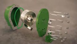
A spiral tube vent condenser consists of a number of tubes stacked and helically coiled. The coiled tubes at each end are welded, soldered or brazed into manifolds or piping that permits fluid to enter and exit the coil. In heat exchanger terminology, this is referred to as the tubeside of the heat exchanger. The coil is placed inside a casing or housing where a baseplate provides for a sealed enclosure creating the shellside that permits fluid to enter and flow along a pathway exposed to the exterior of the coil and then exit the heat exchange area.
A number of advantages are present with such a configuration:
Compactness: The straight length of tubing, which can be 45 feet long, is coiled, resulting in a smaller footprint than a corresponding shell and tube heat exchanger.
Flow path: The path followed by vapors and gases is curvilinear with decreasing radius as flow progresses from inlet to outlet. The curvilinear flow path drives VOCs onto the cold heat transfer surface for effective condensation and elimination from the inert gas stream. This is particularly advantageous when concentration of VOCs is low and velocity is low approaching the outlet of a vent condenser.
Maximized Logarithmic Mean Temperature Difference (LMTD): Fluid flow orientation between hotside and coldside fluids is fully countercurrent, thus eliminating LMTD correction factors for multipass shell and tube heat exchangers. Such an attribute is ideal when heat transfer requires a temperature cross, more specifically, when the hotside is cooled below the coldside fluid outlet temperature.
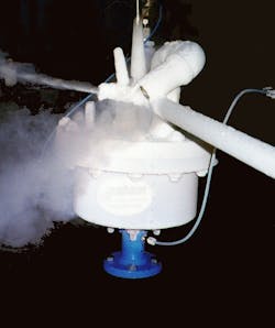
Large temperature differences: The coiled geometry permits handling large temperature variation between the hot and coldside fluid. It is not uncommon to have a cryogenic temperature on the tubeside, such as liquid nitrogen at -280 degrees F, and warm gases on the outside of the tubes yielding a 300- to 400-degree temperature gradient. This coiled geometry characteristic is well suited when thermal growth issues are challenging in shell and tube type heat exchangers.
Three types of configuration: For corrosive applications or condensing mixtures of miscible condensates, vent condensing tubeside (VCT) and condensing within the tubes is ideal. When refluxing condensate directly back into a vessel is desired, vent condensing inside vessel (VCIN) is appropriate. For cases where vent connection on the storage vessel is small, vent condensing on vessel (VCON) style is preferred.
95% and 99% VOC Recovery
It’s common to target 95% reclamation or removal of VOC from a storage tank vent stream. There are cases where targeting >99% removal is the goal. Common chemical industry chemicals were evaluated to illustrate the condenser outlet temperature required to achieve 95% or 99% reduction of a particular chemical in a nitrogen vent stream. The basis is a storage vessel containing liquid chemical at 100 degrees F and 15.7 psia. The vessel is applying a nitrogen blanket over the liquid. The results will not differ materially if the space over the liquid is air rather than nitrogen. Figure 1 depicts a vent condenser outlet temperature needed to achieve 90%, 95% or 99% recovery discharging to atmospheric pressure. For example, methylene chloride requires a 40-degree F vent condenser outlet temperature, whereas hexane requires cooling to 3 degrees F for 95% removal of either methylene chloride or hexane, respectively, from a vent stream.
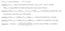
For example, hexane has a vapor pressure of 5 psia at 100 degrees F. The vessel is storing a pure hexane, so the partial pressure of hexane corresponds to its vapor pressure. Further, hexane vapor pressure divided by total pressure will be the mole fraction of hexane in the vapor space.If a hexane storage tank blanketed with nitrogen has 250 ACFM vent stream it has this compositional makeup:
Mass flow rate = 250 actual ft3/min * 0.122 #/ft3 * 60min/hr = 1,830 pph total, of which, 1,080 pph is hexane and the remaining 750 pph is nitrogen
To recover 95% or 99% of the 1080 pph of hexane as condensate, the vent stream must be cooled to 1.8 or -39 degrees F, respectively.It is important to bear in mind the U.S. Environmental Protection Agency Standard RP-42 for organic liquid storage tanks, table 7.1-3, was useful for determining chemical component vapor pressure at typical storage temperatures. Antoine’s equation was used with constants A, B and C given in table 7.1-3. Being that the Antoine equation is a good curve fit approximation of vapor pressure, results of the equation may differ from published vapor pressure data for a particular chemical. Also, the applicable temperature range for Antoine equation constants in table 7.1-3 may not be reasonable for temperature needed to reach 95% or 99% reduction of that chemical in a vent stream.
For example, table 7.1-3 notes for hexane that the range of use for A, B and C constants cited is 55 to 157 degrees F, whereas, hexane needs an outlet temperature of 1.8 or -39 degrees F to achieve 95% or 99% condensation of the hexane, respectively, both outside the cited range. Checking against published data for hexane yielded similar results.
A design for a vent condenser will typically apply published vapor pressure data, where available, rather than use an Antoine equation curve fit for vapor pressure approximation. In the absence of published vapor pressure data, applying Antoine equation outside the cited range may introduce error. It is wise to compare results with published data for vapor pressure.
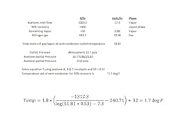
Working with Antoine’s Equation and Standard RP-42, table 7.1-3 information:Thus, if hexane vapor pressure for 95% reclamation, for example, is 0.33 psia, then vent condenser must be designed for an outlet temperature of 1.8 degrees F or colder. The benefit of rearranging to solve for temperature is when a single pure component is the liquid stored then a direct calculation is done for vapor pressure of the component to achieve target reclamation. Once vapor pressure is known, temperature is readily determined. Caution, equations 6 and 7 include units of measure adjustments to yield VP in psia and temperature in degrees Fahrenheit and must only be used in conjunction with constants A, B and C from RP-42, table 7.1-3.
Vent Condenser Heat Release and Mass Balance
For any vent condensing service, it’s important to develop a heat-release curve along with mass balance that defines for a given temperature the amount that is vapor, noncondensible gas and liquid. The approach is to discretize or segment the heat released along the vent stream cooling curve by determining at each interval the amount of condensable vapor that saturates the noncondensible gas (nitrogen or air). It is a process of iteratively resolving equations 1 through 5 at each interval temperature.
This is best illustrated using the following example: An acetone storage tank is at 17.4 psia and 100 degrees F and it is blanketed with nitrogen. Working vent losses control condenser sizing as filling drives the greatest release of vented gas and vapor. The liquid filling rate correlates to 231.5 ACFM vented from the vessel.
Step 1: Determine the amount of acetone that saturates nitrogen at 100 degrees
RP-42, Table 7.1-3 Antoine constants for acetone, A = 7.3, B = 1312.3 and C = 240.71
VPhexane at 100 deg F = 7.47 psia
Yhexane = VPhexane at 100 deg F/Total pressure = 7.47/17.4 = 0.4293
Ynitrogen = 0.4293= 0.5707
MWavg = 0.4293*58.08 + 0.5707*28.02 = 40.9 lb/lb-mole
Density of nitrogen saturated with acetone = 17.4*40.9/(10.73*(460+100)) = 0.1184 #/ft3
Vent stream mass flowrate = 231.5 ft3/min * 0.1184 #/ft3 * 60 = 1648 pph, made up of 1005 #/hr acetone and 643 pph of nitrogen
Step 2: Increment down from an inlet temperature of 100 degrees, determining at each cooler temperature the vapor pressure of acetone and determining the amount of acetone that remains in the vapor phase. Also evaluate the condensing, gas cooling and liquid cooling associated with each step. The greater the increments, the more accurate the LMTD calculation becomes. With a vent condenser outlet temperature between 0 and 5 degrees F, 95% of the acetone is removed from the vent stream. At -40 degrees F, more than 99% of the acetone is eliminated and recovered as liquid condensate.Step 4 – If frosting or ice formation a concern, it’s important to know the freeze point for the VOC being condensed. Evaluate tube wall temperatures to determine if wall temperature is below the freeze point. When liquid nitrogen serves as a coolant, it is not uncommon to experience ice formation, which is detrimental to heat transfer and reclamation efficiency. Should icing be expected, two vent condensers are needed — one in operating mode while the other undergoes defrosting.
Frost or ice formation is a poor conductor of heat and will prevent a vent condenser from achieving required outlet temperature. The equation for determining the wall temperature of a heat transfer surface on the hotside (process side) follows:
Hhotside is the process side heat transfer rate, which varies greatly along the cooling curve. Hhotside is higher at the inlet and lower at the outlet. A lower hotside results in a colder tube wall temperature compounded by the fact that flow is countercurrent and at the process outlet heat is transferred to the inlet coolant where temperature is coldest.
Choice of Coolant
When very cold temperature is needed to achieve required VOC reclamation liquid nitrogen is commonly the coolant of choice. This will yield the smallest unit as it will result in a large LMTD. For the preceding acetone example, the LMTD is 260 degrees F. When ice or frosting is anticipated, two units are needed – one operates as the other defrosts. Secondly, the temperature variation between the hotside and coldside is large, as evidenced by the LMTD. This will result is film boiling that has a lower heat transfer coefficient, countering, to an extent, the benefit of a high LMTD.
Alternatively, there are effective low-temperature heat transfer fluids that may be considered. Using the preceding acetone example, if Syltherm XLT at -70 degrees F inlet temperature is used rather than liquid nitrogen, any concerns regarding ice formation and operating two units can be avoided. The tradeoff is the vent condenser is larger as the LMTD is 94 degrees F rather than 260 degrees F. However, only one vent condenser is needed and controls for two in parallel avoided, though a second heat exchanger is needed to cool Syltherm XLT, which is likely a liquid nitrogen to Syltherm XLT heat exchanger. Industry has used both liquid nitrogen and a low-temperature heat transfer fluid successfully for the coolant in vent condenser service.
The preceding discussion pertained to storage tanks with a pure component, which is the most common scenario. There are cases where mixtures are stored. While the concepts are similar, vapor-liquid equilibrium predictions are more difficult and not addressed herein. Standard RP-42 provides guidance for mixtures.
Chemical and petrochemical companies have options for how to achieve environmental stewardship with respect to emissions vented from storage tanks, including thermal oxidization, adsorption, flaring and condensation or combining technologies. Condensation permits recovering valuable product while also reducing VOC product in vent streams. When addressing vent condensing for single component VOC, there are straightforward methods for determining outlet temperature needed to achieve required reclamation effectiveness. When temperature requirements may result in frosting or ice formation, added care is needed to ensure a design will deliver reliable results.


![Acetone Step 2 Table[59] Acetone Step 2 Table[59]](https://img.chemicalprocessing.com/files/base/ebm/chemicalprocessing/image/2023/01/Acetone_Step_2_Table_59_.63b5b29205f33.png?auto=format,compress&fit=max&q=45?w=250&width=250)

