Enhance Process Hazard Assessment Facilitation
Process hazard assessment (PHA) techniques such as hazard and operability (HAZOP) and what-if evaluations often rely on a facilitator. The methods are structured so the PHA facilitator can do a satisfactory job of identifying hazards even if unfamiliar with plant operations. However, a lack of understanding or appreciation of operational issues can result in a less effective and efficient PHA. So, here, we’ll cover some key aspects of a plant to bolster a facilitator’s grasp of operations and, thus, the thoroughness of a PHA.
First, though, let’s go over the role of a PHA facilitator. The central objective of a HAZOP or what-if assessment is to identify and rank safety, environmental and operability hazards. The facilitator asks pertinent questions to guide the team to think through possible scenarios that could pose risk. Two important issues point up the value of a facilitator having knowledge/familiarity with plant operations:
1. Most PHAs must contend with a time constraint that puts a premium on efficiency. The bottom line is to identify as many hazards as possible, including those with potential high risk, in the allocated time.
2. In the what-if approach, the facilitator develops scenarios to assess. Coming up with the most relevant and robust situations is crucial.
We’ll get into the basics of several types of process equipment — distillation systems, pumps, furnaces, and instruments and control systems — as well as common hazards and mitigation techniques for them. But first, let’s go over some general points that a facilitator should query about any operation to get a quick perspective on hazards:
• Which chemicals are being processed? (The facilitator should refer to the safety data sheets for details on the hazards they pose.)
• What are the ranges of operating temperatures and pressures?
• What safeguards (e.g., relief valves, alarms, interlocks, training manuals and training) are in place?
• What upkeep and redundancy of safeguards is provided? (For instance, in corrosive services, inlet pipes to a relief valve may get clogged and could disable over-pressure protection. How does the plant address that issue?)
• Which systems are required for regulatory compliance?
Now, let’s turn to specific equipment.
Distillation Systems
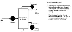
Use of distillation is common at chemical plants and refineries. Briefly put, distillation uses heat to separate a liquid mixture (e.g., crude oil) into its component chemicals based on the difference in their boiling points. Depending on the chemicals handled, distillation could operate at high, medium or low pressures, including vacuum. A distillation system consists of the distillation column itself, an overhead condenser/reflux drum, and a reboiler (Figure 1). The overhead condenser could be water- or air-cooled depending on environmental constraints. The reboiler supplies heat to the column; it could be a furnace (fired heater) or could use steam or hot oil. Distillation systems also include control and safety systems — such as pressure, level and temperature alarms and interlocks to halt the process should an unsafe condition develop. As you can imagine, malfunction of any safety-critical instruments could result in a major mishap.

Figure 1. This common unit operation poses a number of significant risks.
Hazards:
• Hydrogen sulfide, mercaptans, sulfur oxides (SOx), amines and carbon monoxide (CO) are common hazards in oil refinery distillation. In addition, the proximity of other refining operations such as alkylation, fluid catalytic cracking, etc., require consideration of their hazards, which include what the U.S. Environmental Protection Agency (EPA) terms criteria air pollutants (ground-level ozone, particulate matter, CO, lead, sulfur dioxide and nitrogen dioxide) as well as hazardous air pollutants, hydrofluoric acid and greenhouse gases.
• Maloperation of distillation could lead to water hammer (high liquid level in the bottom of the column), which, in turn, could loosen flange connections, eventually causing loss of containment and potential fire or explosion.
• Tube failures in the overhead air cooler could cause a hydrocarbon spill with potential to cause fire. Similarly, tube failures in water-cooled condensers could release flammable hydrocarbons to the cooling tower (if the water side is at a lower pressure than the process side) and could create an environmental compliance problem or the possibility of a fire.
• Distillations involving dirty liquids (e.g., heavy crude) require extensive precautions in emptying and vapor-freeing of the column before issuing a confined space entry permit. Also, pressure relief systems could experience clogging. Some installations rely on rupture discs in addition to relief valves.
• Sudden changes in vapor/liquid traffic could damage column internals. This applies to nearly all processes and must be addressed. Usually, plants rely on control algorithms or procedures to minimize the possibility of rapid changes in vapor/liquid traffic.
Mitigation:
• Ensure operator training/testing, and regular checks of the safeguards/interlocks, especially safety-critical ones.
• Conduct a management-of-change process for major changes in feed composition.
• Implement worker chemical-exposure monitoring.
Pumps
Pumps impart pressure or potential energy to move liquids. Chemical plants and refineries usually rely on centrifugal pumps to transport liquids with viscosities below 650 cS and positive displacement pumps for more viscous liquids.
A centrifugal pump system consists of a suction line, a pump casing containing an impeller, a discharge line, bearings and a mechanical seal. An operating (head/flow) curve characterizes pump performance. As flow increases, pressure decreases to an extent that depends on the impeller design. Pump efficiency reaches a maximum at a certain flow rate and head (pressure) called the best efficiency point (BEP). Although running at the BEP is most desirable, process conditions may dictate operation below or above the BEP and, hence, at lower efficiency. If the discharge valve is completely closed, the pump develops the highest pressure, which is called “dead head” pressure. Discharge pressure can’t exceed the deadhead pressure unless extended operation at blocked flow causes liquid to vaporize.
Cavitation is a dangerous phenomenon with centrifugal pumps. Briefly put, cavitation occurs when low suction pressure vaporizes liquid entering the pump. As the impeller turns, vaporized liquid (typically vapor bubbles) collapses, releasing tremendous energy that could destroy the impeller or even the pump housing, mechanical seal and bearings. Release of flammable liquid from the pump could cause a fire or an explosion while escape of toxic liquid could threaten the health of workers. Often, releases have simultaneous adverse impact on the environment.
Positive displacement pumps come in several designs including gear pumps and piston pumps. Unlike a centrifugal pump, a positive displacement pump doesn’t have a certain fixed dead-head pressure. If the discharge valve is blocked, a running pump keeps increasing discharge pressure until a component of the system fails.
Pump systems include alarms and interlocks to warn operators of unsafe operations. Generally, these systems are reliable. However, dirty/viscous liquid services demand periodic monitoring of these safeguards.
Hazards:
• Low or no flow operation could cause a centrifugal pump to overheat and release liquid to the environment. Many sensitive pumps feature low flow alarms or spillback recirculation (low flow recycle).
• Cavitation is a risk with centrifugal pumps.
• No flow or blocked operation of positive displacement pumps could lead to rapid pressure rise and eventual loss of containment.
• Pumps could suffer reverse flow.
Mitigation:
• Ensure all safeguards are in proper working condition.
• Specify air-fail-open for the spillback flow valve. Preferably, the spillback line shouldn’t contain a block valve because its inadvertent closing would completely defeat the purpose of spillback.
• Never allow operation of a positive displacement pump with a closed discharge valve.
• For a piston-type positive displacement pump, use suction and discharge snubbers to minimize pressure surges and, hence, resulting vibration. (In some cases, severe pressure surges have damaged piping and released hazardous liquids.)
• Avoid operation under cavitation. (A common indicator of cavitation is a sound like pumping of marbles.) Operators deal with cavitation by raising liquid level in the suction tank, cooling the liquid going to the pump, or reducing flow rates. Other approaches focus on ensuring the net positive suction head available remains greater than that required.
Furnaces
Furnaces heat fluids to high temperatures, typically above 800°F. In a furnace (Figure 2), fluid enters the convection section and flows successively through the shock bank and radiant sections. Generally, a temperature controller at the outlet of liquid flow regulates the fuel and air flow to the furnace. Combustion of fuel (e.g., natural gas, fuel gas, oils and their mixtures, etc., depending on the particular plant) provides the heat to the fluid. Flue gases or products of combustion exit the furnace through the stack. Some heaters require periodic stack testing for air emissions following procedures specified by the EPA or a state agency.
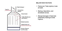
Figure 2. The process of burning fuel to provide heat raises a number of risks.
Furnaces operate under a sight vacuum (-0.4 to -0.5-in. water at the radiant section), called draft, which the interaction of damper and air registers controls. Natural draft furnaces use atmospheric pressure to create air flows. Mechanical draft furnaces, which tend to be larger, use fans to control air flow and draft. Generally, the amount of air used slightly exceeds the stoichiometric amount because furnaces rarely have complete mixing of air and fuel — the more excess air, the lower the furnace efficiency. Air less than the stoichiometric amount, which is called deficient air, is dangerous, as it can lead to an explosion. Another dangerous situation is flameout, a condition in which all burners lose flame. Furnaces have various monitors, e.g., to check for the presence of flames, analyze flue gas and CO level, and measure furnace tube temperatures. Some furnaces use special burners called low NOx burners to minimize NOx emissions.
Hazards:
• Unless addressed quickly, flameout and deficient air operation could cause an explosion.
• Normally, flames from burners aren’t supposed to touch or impinge on a tube. However, if a burner is improperly installed or damaged, its flame could impinge on tubes. Flame impingement is tolerable for a short time and doesn’t require an immediate shutdown of the furnace. Generally, operators pull out the defective burner, and then clean it or put in a new one.
• Stack thermocouples provide a good indicator of furnace operation. With some sulfur-containing fuels, stack temperatures below 360°–375°F could cause severe corrosion of convection tubes or the stack lining. An abrupt rise in stack temperature could indicate a tube rupture.
Mitigation:
• Proper training as well as periodic checks of safety critical instruments and interlocks and the burner management system are highly recommended. Operators also should inspect flame shape and color as a part of the shift rounds.
• Conduct a management-of-change procedure whenever a major change in feed to the furnace occurs.
• Before every startup, remove any flammable vapors left in the furnace by thorough purging (generally with steam). This process is called the purge cycle.
• Use control algorithms to minimize abrupt changes in flow rates (charge) to the furnace.
•For multi-pass furnaces, install reliable pass flow indicators with flow alarms.
Instruments And Controls
Malfunction of instrumentation or process control systems could result in major safety or environmental mishaps. So, let’s briefly look at a number of key points.
The most common instruments are for measuring flow, level, pressure and temperature. Reasons for their malfunction include misapplication, sub-standard installation, improper use (i.e., beyond rated range), and poor or inadequate maintenance. In addition, interaction among parts of a control loop can cause unsafe situations. For instance, the controller regulating the temperature of a reactor gets a signal from a transmitter and then, if necessary, adjusts a control valve. Collectively or individually, a transmitter that isn’t working right, an improperly tuned temperature loop, or a malfunctioning (say, sticking) control valve can prompt high swings in reactor temperature. In some cases, extreme high temperature could lead to runaway reactions that, in turn, could cause a fire or explosion.
Appropriate instrument selection, installation and application are crucial. One common approach is to provide redundant instrumentation to enhance system reliability and safety. Plants seldom go beyond triple redundancy. Redundancy presents an interesting paradox: it improves safety but, at the same time, also could cause spurious shutdown that would defeat the overall safety objective.
One critical issue with instruments is what’s known as a common cause problem. For example, often multiple pneumatically actuated control valves get air from the same compressor. Any problem with air supply will affect all the valves. One approach with safety-critical systems is to provide a dedicated air supply. In addition, configuration should ensure control valves fail in safe position on loss of air.
A related issue is common mode failure, where two systems fail in the same way for the same reason. Common cause problems may create common mode failures. One way to deal with these problems is deploy independent systems — e.g., instruments using different technologies and powered by separate sources.
Hazards:
• Instrument and control system failures can cause major adverse consequences. So, proper selection, installation and upkeep are essential.
• Too many alarms could distract operators and cause safety/environmental mishaps. A process called alarm rationalization can weed out unnecessary or nuisance alarms.
Mitigation:
• Provide multiple layers of protection to minimize the likelihood of an unsafe event. Obviously, their upkeep is very important for enhancing safety and regulatory compliance.
• Prior to commissioning instrument/control systems, perform a HAZOP analysis to identify weak spots and then take proper corrective action.
The Facilitator Matters
A facilitator with working knowledge of operating systems will enhance the efficiency and effectiveness of a PHA. Coupling such a person with a seasoned PHA team will help achieve the common goal of minimizing risk.
GC SHAH, PE, CFSE, CSP, CFPS, is a Houston-based consultant specializing in process safety, plant operations/analysis/troubleshooting, including hazard analysis and fire protection services. Email him at [email protected].