- Process Analysis Gains Greater Online Roles
- Smaller, Smarter Systems Streamline Sampling
- NeSSI’s Success should be a Lock
- For more information on the specifications: NeSSI Generation II specification
- CANopen specifications, frameworks, and profiles
- CiA DS 404 V1.2 (CANopen device profile measuring devices and closed-loop controllers)
The New Sampling/Sensor Initiative (NeSSI) has provided the basis for modular miniaturized process sampling systems that offer ease of assembly and flexibility while cutting cost of ownership. Not surprisingly, plant acceptance of such NeSSI systems is growing.
A group of analyzer specialists now is working to enable NeSSI to be used in hazardous environments. They envision an analytical system with smart transducers that would be capable of being field mounted at the sample point in a potentially explosive atmosphere and would be easily integrated into the analyzer control system.
To operate safely in a hazardous/combustible environment, the transducers in the sample handling system require an Intrinsically Safe (IS) bus to communicate with the analyzer controller. Such a bus must use very low power to prevent any type of ignition. However, adoption of a standard IS bus has been difficult because none of the existing industrial networks exactly fit all the analyzer specialists’ requirements for a simple, small, inexpensive as well as IS transducer bus.
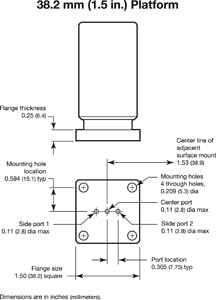
Figure 1. Standards for dimensions enable easily switching single devices without need to modify others. Derived with permission from ISA, www.isa.org.
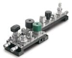
Figure 2. This sample-handling and preparation system illustrates the size of surface-mount fluid distribution components of NeSSI.
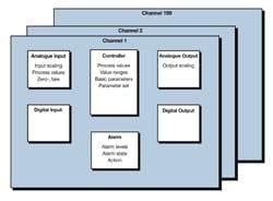
Figure 3. CANopen provides device profiles and function block descriptions. Source: CiA.
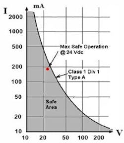
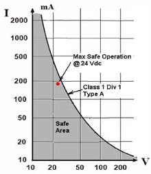
Figure 4. Bus operating at 24V dc significantly limits current available to IS device.
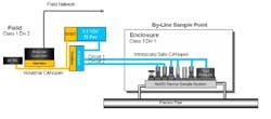
Figure 6. Plants trials will demonstrate use of IS CANopen with a NeSSI system.
So, as an alternative, the group looked at Controller Area Network (CAN) communications technology. This is low cost and can be implemented with low-power bipolar and complementary metal-oxide semiconductor (BiCMOS) electronics and proven CANopen device profiles. The group recently completed definition of an IS version of CANopen to meet its transducer bus requirements, resulting in an emerging standard — CiA 103 DSP V1.0.
Historical backdrop
For more than 50 years, plants have relied on process analytics to decrease costs, lower staffing levels, improve quality and increase throughput. Analyzers have evolved into sophisticated chemical sensors and automation instruments that have migrated from the laboratory to the field for integration into real-time process control systems. However, the front-end designs of analytical systems — sample handling and preparation — haven’t appreciably improved for many years.
A1999 ISA symposium spurred an effort to radically rethink such system designs that led to the creation of NeSSI. A consortium of end-users, suppliers and schools, working under the umbrella of the Center for Process Analytical Chemistry at the University of Washington, Seattle, developed the vision and specifications for NeSSI sample systems, including: 1) modular miniaturized sampling components; 2) smart transducers; 3) field mounting capabilities at the sample point in potentially explosive atmospheres; and 4) easy integration into plant control systems.
The NeSSI specification defines two interface “rails” that allow for easy system integration. A fluid rail enables modularity by providing a standard interface to connect flow paths between devices. A bus rail enables the smart transducer and field mounting capabilities by providing IS power and digital communications between the smart sampling system components, the analyzer and the process control system.
In August 2002, a 1½-in. square NeSSI component footprint for the fluid rail was adopted in the ANSI/ISA 76.00.02 standard, which defines properties and physical dimensions for surface-mount fluid distribution components (Figure 1). This fixed footprint enables changing a single element without having to modify the entire system, streamlining design and maintenance.
Adoption of ANSI/ISA 76.00.02 led to the emergence of what are referred to as NeSSI Generation I miniature modular sample systems. Their modular platform components consist of a surface-mount layer made up of devices such as valves, filters and adapters; a substrate layer that provides the flow path between the surface-mount components; and a manifold layer that provides the flow path between two or more parallel substrates (Figure 2).
With the fluid rail standard established, the NeSSI consortium turned its attention to the bus rail, publishing the NeSSI Generation II specification. This calls for upgrading the traditional manual rotometers, gauges and metering valves used in sample systems to smart pressure, temperature and flow sensors that are automated, have self-diagnostic capabilities and are plug-and-play. The new sensors and proposed family of intelligent valves would monitor and operate the sample handling and preparation processes under the supervision of the analyzer controller or the analyzer itself.
With many of the NeSSI systems expected to be deployed in the potentially explosive atmospheres common in process plants, the consortium identified an IS transducer bus as the key technology for Gen II to become a reality. Unfortunately, the adoption of an IS NeSSI bus standard hasn’t come as easily as the fluid rail standard.
The bus conundrum
On the surface, choosing an open-standard IS transducer bus seems to be a simple choice of one of four possible automation protocols: Foundation Fieldbus, Profibus-PA, HART or ControlNet, all of which already are established in the process and manufacturing industries. However, the NeSSI consortium discovered that none of these buses was particularly well suited for the types of smart devices that would populate a NeSSI Gen II system. The consortium had concerns about architecture complexity, physical size and cost of these options.
Architecturally, existing IS buses don’t match the simple design of NeSSI devices. Typically, IS buses are designed to operate a few sophisticated devices using complex messaging protocols over long distances (e.g., 1.9 km for Foundation Fieldbus), with a determinism suitable for real-time control. Relatively speaking, NeSSI systems aren’t time critical. Gen II components are simple sensors and actuators that support basic configuration and diagnostic functions — and don’t require such a complex messaging protocol. Further, NeSSI devices communicate with a local controller usually located less than 10 m. away.
On the size front, the 1½-in. square ANSI/ISA 76.00.02 footprint places a serious constraint on the amount of electronics that can be fitted onboard a NeSSI Gen II device. The major IS buses, with the exception of HART, require at a minimum: a relatively powerful microcontroller, a protocol controller Application-Specific Integrated Circuit (ASIC), a bus interface and driver circuits. The size and number of required electrical components make it difficult, at best, to squeeze an IS bus — along with the requisite input/output (I/O) circuitry, connectors and other miscellaneous electronics — into the NeSSI footprint.
Lastly, the relative cost of the IS buses is high compared with NeSSI devices. The IS buses were designed to be deployed in larger process control valves and transmitters in which the bus technology represents a fraction of the device’s total cost. NeSSI devices typically cost much less than larger process control valves or transmitters, making the cost of a smart NeSSI device that uses one of the IS bus technologies much higher than its non-networked counterpart.
Other industries, such as semiconductor, consumer electronics and automotive, use simpler, smaller and less expensive buses such as USB, I2C and CAN, which would be ideal for use as the NeSSI bus; however, these options aren’t intrinsically safe.
Given these choices, decision-makers were faced with a conundrum: Do they make one of the IS buses simpler, smaller and less expensive, or do they make one of the simpler, smaller and less expensive buses intrinsically safe?
A solution emerges
The NeSSI bus market is relatively small compared to others. So, it would be unrealistic to imagine that any one company would allocate resources to develop an IS transducer bus specifically for NeSSI. From the outset, the NeSSI visionaries realized they would need to build on existing bus systems and reuse as much commercially available technology and infrastructure as possible to have a realistic chance of success.
A key requirement of a NeSSI bus is that it be an open standard, available to the general public (not necessarily free of charge). To ensure compatibility, interoperability and multi-vendor component interchangeability, a bus must adhere to the three layers included in the Open Systems Interconnection (OSI) Layer Reference Model (ISO 7498). Typical industrial communications protocols implement the following three OSI layers:
- The link layer, usually implemented in protocol controller ASIC, defines the control bytes and their use in transporting the data;
- The application layer, usually implemented in software, defines the meaning of the data bytes
- The physical layer defines the electrical signals, their timing and their transport media (i.e., wiring, connectors, etc.).
The link layer posed two principal concerns — cost and size (or miniaturization) of the ASIC. The cost of integrated circuits is proportional to their quantity and complexity. CAN, originally developed by Bosch for the automotive industry, is a link layer specification implemented in ASICs and microcontrollers produced in huge quantities — more than 500 million CAN chips are sold each year. With high production volumes and simple architecture, CAN network controllers often are included on simple 8-bit microcontrollers costing less than $5. Further, with the communications controller embedded in the same IC as the microcontroller, the miniaturization achievable with the CAN protocol is unparalleled by any network requiring separate protocol and processing ICs. These characteristics make CAN a good choice for the NeSSI bus link layer.
The principal challenge with the application layer was to ensure interoperability and enable interchangeability in an open multi-vendor environment. CAN in Automation (CiA) members have developed a number of device profiles that specify how transducers and closed-loop controllers connect, enabling a plug-and-play network. CANopen device profiles such as DS 404 V1.2 describe devices for measuring or controlling loops of different physical quantities. Also defined are function block descriptions of digital input, analog input, digital output, analog output, controller, alarm and device functions (Figure 3). Availability of CiA device profiles made CANopen a good choice for the NeSSI bus application layer.
Given the suitability of CANopen link and application layers, intrinsic safety remained the only issue to be resolved. The suitability of a system for IS applications is determined largely by its external electrical signals, which in a communication system are defined in the physical layer specification.
In the physical layer, the principal challenge was to define bus operation at a low enough voltage and current to ensure the bus would be intrinsically safe. Field buses are designed to work over long distances; therefore, their bus voltage must be high (nominally 14–24 V dc) to accommodate the signal attenuation due to the high impedance associated with long wire runs. However, long wire runs aren’t required in NeSSI systems, so the line impedance is lower, decreasing the potential signal attenuation.
This means the NeSSI bus can operate with much lower voltage than field buses. In a NeSSI system, networked devices are clustered in a small area, usually less than 3 ft × 3 ft, and typically are closer than 10 meters to a safe area. The NeSSI consortium realized that this short physical network length meant bus voltage could be reduced significantly from the standard 24 V dc required to drive signals up to a mile or more. The short distance of the NeSSI bus permits a more manageable 10 V dc voltage, allowing a fivefold increase in the power budget while maintaining IS feasibility (Figure 4).
New BiCMOS technology enables low-power CAN electronic systems that use about one-third the power of ISO 11898 CAN driver circuits. Further, the BiCMOS CAN driver components remain compatible with existing CAN systems. Thus a NeSSI bus solution seemed within reach. By placing restrictions on the wiring distance and using BiCMOS drivers, CAN would be made suitable for IS applications.
Moving ahead
However, further progress had to wait until the NeSSI consortium could get a standards organization to take ownership of the proposed IS CAN physical layer development and specification. Finally, in 2003, a NeSSI workshop, hosted by the National Institute of Standards and Technology, uncovered the opportunity to address the issue of ownership. A new project — known as IEEE P1451.6 — had just been commissioned to harmonize the IEEE 1451 family of smart transducer interface standard Transducer Electronic Datasheets (TEDS) with the CANopen standard device profile DS 404. As a result of this workshop, an option to define a low-power physical layer interface to address the NeSSI IS requirement was included in the IEEE P1451.6 project.
In March 2006, the NeSSI consortium transitioned the IS CAN project into the CiA and composed Working Draft 103, “CANopen Intrinsically Safe Physical Layer,” which, after comment and refinement, was released as Draft Standard “CiA 103 DSP V1.0: CANopen intrinsically safe capable – Physical layer specification.” It’s available on the CiA Web site (www.can-cia.org/downloads/ciaspecifications/).
CANopen, with the 103 DSP specification, has become the NeSSI bus solution envisioned nearly six years ago. Today, CANopen IS transducer bus NeSSI systems are in the process of development and evaluation in a number of pilot projects (Figure 5).
Broad promise
The NeSSI consortium has shown that a low-cost transducer bus can be intrinsically safe. CiA device profiles and CANopen conformance testing furnish the infrastructure by which transducer vendors can offer certified plug-and-play multi-channel devices for cost-effective sensor and actuator solutions. The CiA also provides a forum for special interest groups, such as NeSSI, to adjust the CANopen protocol to meet their specific industry requirements. Emerging standards such as CiA 103 DSP V1.0 make a strong case for end-user adoption of a CAN protocol in hazardous process environments.
The process industries won’t be the only beneficiary of the CiA IS CAN standard. It’s a technically viable solution for many other applications. Opportunities for IS systems can exist where CAN-open communications are already deployed, such as for paint booth robots in automobile manufacturing. If CiA IS CAN is added to the ISO 11898 family of standards, it will enable other CAN-based automation protocols with intrinsic safety. The future for IS CAN is promising.
Rick Ales is product manager at Swagelok Co., Solon, Ohio. E-mail him at [email protected].
