Minimize Gas Chromatograph Downtime
Processors have relied on gas chromatographs (GCs) since the 1950s to provide real-time compositional data to control systems. Today, tens of thousands of GCs serve in a diverse range of plants — making the GC the analytical workhorse for online compositional measurements. The performance of these devices critically impacts the quality of the final product, the efficiency of plant operations and, ultimately, the bottom line.
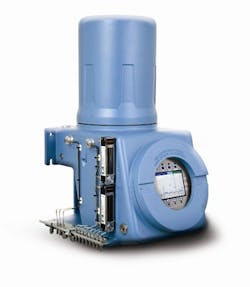
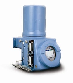
Figure 1. Units such as this provide compositional data crucial to maintaining product quality and efficient operations.
The GC’s important role means that its downtime should be kept to a minimum and planned ahead of time, rather than taking place only when a failure has occurred. While maintenance may seem like an issue for technicians, in fact, it becomes a management problem when it so directly impacts profitability. Therefore, every plant manager should understand GC maintenance and troubleshooting practices and use them to establish a meaningful maintenance program and provide effective training. Ideally, the maintenance program should identify analysis problems before they cause measurement errors — allowing maintenance to be performed on a predictive rather than an ad-hoc or breakdown basis.
Here, we’ll look at maintenance best practices for both key elements of a GC setup — the sample handling system and the analyzer.
[callToAction]
Sample Handling System
This system not only is crucial to the correct operation of the analyzer but also accounts for most of the physical maintenance required in a GC setup.
The role of the sample handling system is to:
• take a representative sample of the gas;
• remove particulates and free liquids;
• control the sample pressure, so that it’s within the analyzer specifications, usually between 10 psi (70 kPa) and 20 psi (140 kPa);
• transport the sample to the analyzer, maintaining its gas phase and composition;
• provide switching between sample streams and the calibration gas stream; and
• vent the sample to atmospheric pressure.
If the sample handling system is performing all these functions correctly, then the GC will operate reliably as designed and only will require downtime when the diaphragms eventually wear. Maintenance often isn’t necessary for 18 months or more when the sample system cleans and dries the sample correctly. Diaphragm wear can be identified, enabling overhaul on a planned basis.
The frequency of maintenance on the sample handling system somewhat depends on the location and quality of the gas being measured. Analyzer installations that are inside a production facility usually are very susceptible to contamination because they are exposed directly to process upset; thus, they will require frequent maintenance to maintain the integrity of the measurements. Installations that are at the final delivery points of the process will need less frequent maintenance because many of the contaminants will have been removed.
The following steps provide the basis for a maintenance and troubleshooting program for a chemical plant:
1. Frequent maintenance (from daily to monthly, depending on operating conditions and previous history):
• Check sample pressure. Verify sample pressure is set as commissioned. Note that a blockage on the primary filters of the sample probe can cause a lower-than-normal sample pressure. Setting the sample pressure at the probe higher than the required pressure at the GC can overcome the pressure drop in the sample lines.
• Check sample flows. Watch the sample flow rotameter as each sample is analyzed. While different flow rates or pressures don’t affect analysis on units that equalize the sample to the atmosphere, a change in the flow rates may signal that the filters are becoming blocked. Low sample flow also can indicate a blocked or pressurized vent line.
• Check sample line heat trace. Confirm the heat trace is working. Often all this involves is verifying that the sample line at the furthest point (usually at the sample probe) is warm to the touch.
• Check bypass flow rates. The flow rate through the bypass flow loop should be double that of the sample outlet. Inspect the cleanliness of the glass in the bypass rotameter. Contamination there indicates the entire sample line from the probe to the GC is contaminated and needs to be flushed.
• Check calibration gas bottle pressure. It should exceed the minimum pressure specified on the calibration gas bottle certificate (typically 70 psi or 500 kPa).
• Check carrier gas bottle pressure. Ensure that both carrier gas bottles have sufficient pressure to last until the next routine maintenance inspection.
2. Less frequent maintenance (from monthly to every six months):
• Remove the sample probe and install a new moisture membrane filter (if fitted) and primary filter.
• Replace the particulate filter cartridge.
• Change the membrane in the moisture filter/shutoff.
3. System overhaul (done when conducting maintenance on the GC, whether planned or due to breakdown):
• Perform all the steps listed under less frequent maintenance.
• Flush the entire sample line(s) with acetone or isopropyl alcohol, and dry with helium.
• Leak-check all the connections throughout the sample handling system.
The Analyzer
Routine maintenance on the GC analyzer (Figure 1) primarily involves performing diagnostics and making small changes to timed events to allow tracking the gradual increase in the retention time due to contamination and wear in the analysis valves. When the diagnostics indicate a large shift in retention times from the last overhaul or a dramatic increase in valve noise, then an overhaul of the analysis valves can be planned for a convenient time.
All routine diagnostics can be performed over a remote connection, saving considerable expense in travel time for the service engineer. Alarms can be configured so notifications can be sent via e-mail or text. Software now available automatically can handle the mundane collection of the diagnostic information on a routine basis (say, early every morning well before the work day starts), reducing the time needed to perform these diagnostics and providing a full audit trail of the information.
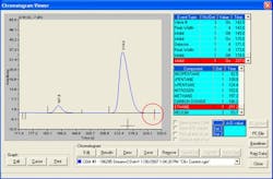
Figure 2. Tail of last eluted component peak being close to the end of the analysis time indicates need for valves’ overhaul, not longer analysis time.
Here are routine diagnostics steps to take:
1. Download and check several items:
• Alarm log. An alarm indicates an issue and, so, demands follow-up.
• Event log. It shows any changes made manually and provides an audit trail of changes made to the system.
• Final calibration report. The response factor deviations shouldn’t be excessive. While the GC normally will produce the infamous “RF Deviation Alarm” if the deviation surpasses 10%, a shift of greater than 5% indicates the analysis is changing, especially if it is only in one component. Also check the response factors; they should be in the same order as the component thermal conductivity (at 80°C).
• Calibration chromatogram. Look for a smooth baseline and good detection of the start and end of all peaks. Confirm the retention times shown in the component data table match the retention times shown on each peak of the chromatogram.
• Sample chromatogram of each stream. Examine the un-normalized total. Un-normalized totals that change more than 0.5% across streams can indicate the sample shutoff valve isn’t sealing. In such a situation, the un-normalized total will become dependent on the sample pressure.
2. Compare the current calibration chromatogram with a previous chromatogram. The current calibration chromatogram may be analyzing perfectly — however, the GC may have adjusted itself automatically to small shifts in the retention times. Comparing the current chromatogram to one saved immediately after a valve overhaul (or from the factory) will show the total amount of shift in the retention times and other changes in operation. Important details to look for include:
• The retention times have shifted by more than 10 seconds. This indicates an increase in the restriction to flow provided by the analysis valve. Overhaul the analysis valves and the sample shutoff valve.
• The tail of the last eluted component peak is approaching the end of the analysis time, as seen in Figure 2. This isn’t a sign to lengthen the analysis time! The restriction to flow has increased, so the analysis valves and the sample shutoff valve need overhaul.
• The tail of a component peak is approaching the “inhibit off” time (Figure 3). Once again, this shows the restriction to flow has increased and the analysis valves and the sample shutoff valve require overhaul.
• The valve noise from the switching of each of the analysis valves is interfering with peak detection. If the valve noise exceeds the baseline of the smallest peaks, then schedule overhaul of the analysis valves and the sample shutoff valves.
Adjustments to valve timing and other timed events to overcome the effects of an increase in the restriction can be made and the overhaul of the valves can be performed at a time convenient to the operation of the plant; however, this is a short-term measure. Once the valves have begun to be contaminated, the shift in retention times will tend to increase at a faster rate.
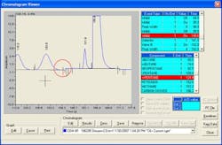
Figure 3. The tail of a component approaching the “inhibit off” time (shown by red line) signals that valves require overhaul.
GC Maintenance
The normal maintenance of the GC can take place either on a routine basis or when the diagnostics indicate an issue.
Approximately 80% of all GC maintenance involves overhauling analysis valves and the sample shutoff valve (a diaphragm-style valve needs only about $100 in parts, so the repair is very cost effective). An often-overlooked component of this overhaul procedure is the sample shutoff valve. Treat any contamination of the analysis valves as proof of contamination of the sample shutoff valve as well, because the sample is flowing through it 100% of the time. Therefore, when servicing the analysis valves, overhaul the sample shutoff valve, too.
Other maintenance that may need to be performed includes the replacement of the solenoids (valve actuation or stream selection) due to electrical failure or mechanical wear. On very rare occasions when a complete and catastrophic failure of the sample handling system has left a large slug of liquids in the sample stream, then an “oil change” may be required. This involves:
• overhauling the analysis valves and sample shutoff valves;
• decontaminating the sample system and oven tubing;
• replacing the columns; and
• installing new detectors.
Any maintenance procedures that require replacement or overhaul of a component in the analysis flow path will necessitate adjustment of the valve timings and timed events to account for the change in the restriction to flow. The person performing the mechanical repair, or a specialist over a remote link, can make this adjustment.
Analyze Your Program
Most of the routine maintenance of a GC system involves the sample handling system. The reliability and accuracy of the GC analyzer totally depends on the sample being clean and dry; so focus most effort on achieving this goal, rather than spending excessive time and effort dealing with the consequences of poor sample handling. While the GC does require some maintenance (due to eventual contamination and mechanical wear), this usually is confined to a simple valve overhaul procedure requiring very inexpensive components or solenoid replacement. Routine diagnostics, which can be performed remotely, provide the best indicator of when maintenance is needed. Armed with this basic knowledge, a plant manager can establish a realistic GC maintenance program that improves operations and saves money.
BONNIE CROSSLAND is Houston-based product manager for Rosemount gas chromatographs at Emerson Process Management. E-mail her at [email protected].