Upgrade Your Safety Instrumented Systems

Reliable safety instrumented systems (SISs) that robustly protect personnel, assets and the surrounding environment are vital to the safe operation of chemical plants. Many facilities rely on legacy, often decades-old, SISs. Despite this, these systems continue to provide a dependable layer of protection in compliance with the International Electrotechnical Commission’s IEC 61508 and IEC 61511 standards relating to functional safety. Some chemical makers adopt an attitude of “if it isn’t broken, don’t fix it” and do not consider upgrading to modern instrumentation. With tight operating budgets and limited resources, this seems perfectly reasonable — but it means these companies are missing out on the opportunity to enhance safety and lower lifecycle operating costs.
The reluctance to modernize commonly stems from the perceived cost and complexity of replacing old instrumentation with new units. However, to reduce complexity, the latest flow, level, pressure and temperature measurement devices suitable for integration into SISs have been designed to ease their installation and use. Crucially, they feature enhanced functionality that provides a range of significant benefits, such as smart diagnostics suites and remote proof-testing capabilities. This functionality helps increase plant and personnel safety, and decrease maintenance costs and downtime, which typically leads to a quick return on investment.
Let’s look at some specific aspects of this enhanced functionality in modern SIS instrumentation and the important benefits achievable.
Proof Testing
SISs are designed to perform a safety instrumented function (SIF). This requires three elements: measurement sensors that monitor the process; logic solvers that evaluate the sensor input to assess whether the process is running safely; and final control elements (very often valves) that safely shut down the process when necessary.
An SIF should use the most-reliable components. Recognized standards (e.g., IEC 61508) define methodology for assessing device reliability. A third party generally performs these assessments, although manufacturers also are allowed to conduct self-assessments (IEC 61511). The methodology considers the design of the device to determine its inherent susceptibility to fail in the first place. Obviously, this is the most robust way to ensure reliability. The methodology then assesses potential failures considered “safe” and failures detected through diagnostics. Assessing any remaining potential failures requires periodic proof testing.
Proof testing verifies that, when a safety demand arises, equipment will work correctly, achieving its required safety integrity level (SIL) for the application. It involves testing each component individually as well as the complete safety loop. A safety loop’s probability of failure on demand (PFD) increases over time. Performing a proof test resets the PFD to a lower value and ensures the safety loop provides the expected risk reduction. The PFD average of the safety loop determines the frequency of proof testing. A technical justification, such as the PFD calculation, can enable extending the interval between tests.
A plant can perform two types of proof test — comprehensive and partial —in compliance with the relevant industry standards, IEC 61511 and API 2350. Comprehensive proof tests involve testing the entire safety loop in a single procedure, to ensure all its parts are functioning correctly. This will return the PFD of the safety loop back to, or very close to, its original level. A partial proof test may include one or several parts of the safety loop and will bring the PFD of a device back to a percentage of the original level.
Performing a partial proof test can provide significant benefits. Such a test is quicker to complete, interferes less with operations and, crucially, justifies an extension of the time interval required between comprehensive tests while remaining within regulatory requirements. This extension may allow scheduling the comprehensive test during a planned shutdown, thus increasing plant availability and efficiency.
Proof testing traditionally occurs on location. However, the digital technology available in modern level-measurement devices enables performing partial proof testing remotely; the devices remain installed while simulated overfill conditions activate the detector and generate an alarm signal. Use of simulation makes moving fluid into and out of the tank to conduct the test unnecessary and avoids the risk of spills. It also eliminates the need for workers to climb tanks (Figure 1) or be exposed to tank contents, thereby increasing their safety and freeing them up to concentrate on other value-added tasks. The ability to perform partial proof testing remotely has become a key selection criterion when implementing level measurement technology as part of an SIS.
Detecting Plugged Impulse Lines
Advanced diagnostics in modern pressure transmitters can detect many abnormal conditions in processes, including plugged impulse lines, which are an all too common problem. These lines — small-diameter tubes or pipes used to transmit the pressure signal from the process to the transmitter — can become plugged with solids or frozen fluid in cold environments, which effectively blocks the signal and prevents measurement of a change in pressure (Figure 2). The transmitter will continue to provide the same pressure reading as before the blockage; by the time this misleading measurement has been discovered, the plugged impulse line already may have compromised safety.

Figure 1. Remotely performing partial proof testing eliminates the need for staff to climb tanks.
To meet this challenge, a statistical processing technology has been developed that enables early detection of abnormal situations, including plugged impulse lines, in a process environment. The technology is based on the premise that virtually all dynamic processes have a unique noise or variation signature when operating normally and that deviations in these signatures may indicate a significant change in the process, process equipment or transmitter installation will occur or already has. For example, noise may come from equipment such as pumps or agitators, the differential pressure value may show natural variation caused by turbulent flow, or the signature may reflect a combination of both sources.
The sensing of the unique signature begins by using a high-speed sensing device combined with software to compute statistical parameters that characterize and quantify the process noise or variation. This enables the device to detect significant changes in process noise or variation and then communicate an alarm notifying operators of an abnormal situation. Such early warning allows maintenance technicians to resolve the issue before it affects safety.
Signal Quality Metrics
In some level-measurement applications, monitoring for changing surface conditions is critical. Unwanted foam, boiling or emulsions can lead to a spoiled batch, while surface changes that go unnoticed could result in overfilling. Because the materials involved can be hazardous, flammable and even explosive, an overfill potentially can put personnel at risk and cause significant damage to assets and the environment.
When batch processes require both level and surface-condition monitoring, plant personnel may rely on multiple measurement methods. This incurs additional maintenance and calls for more process connections. If a vessel is limited to only one process connection, staff may resort to manual or visual methods of monitoring surface conditions, which can be both time-consuming and unreliable.
To help monitor changing surface conditions, the latest radar transmitters include diagnostics based on signal quality metrics; signal quality values range from 0 to 10, with 10 representing a strong signal and no process noise. A significant change in the signal quality value might indicate changing surface conditions. For instance, if foam is present, the signal quality would drop in value. By sending level and signal quality to the control room as process variables, operators there can monitor these parameters over time. Crucially, this can enable the operators to quickly recognize an unwanted surface change, thus increasing safety by reducing the risk of tank overfills caused by these conditions. Such early detection also helps to maintain high-quality batches and avoid waste or rework, which would cut throughput and raise operational costs.
Ground And Wiring Fault Detection
Magnetic flowmeters used in SISs must operate accurately over long periods of time. Flowmeter failure can prevent the SIS from performing as required and necessitate a process shutdown, thereby reducing throughput and profitability. However, issues sometimes can arise. The number one cause — primarily in new installations where the magnetic flowmeter is not referenced correctly to the process fluid — is improper grounding and wiring. This allows the electrodes to pick up electrical noise and, consequently, affects the signal-to-noise ratio and the stability of the transmitter output.
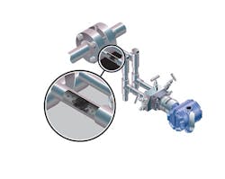
Figure 2. Small-diameter tubes or pipes used with pressure sensors can fill with solid material or freeze in cold environments.
Modern devices feature a ground- and wiring-fault detection diagnostic. If the installation is not grounded or wired properly, the diagnostic will activate, delivering an alert to carefully review the grounding and wiring of the installation. It also can detect if the grounding is lost over time due to corrosion or another root cause.
The transmitter continuously monitors signal amplitudes over a wide range of frequencies. For the ground- and wiring-fault detection diagnostic, the transmitter specifically looks at the signal amplitude at 50 Hz and 60 Hz, the common AC cycle frequencies found throughout the world. A signal amplitude at either of these frequencies exceeding 5 mV indicates a ground or wiring issue exists and stray electrical signals are getting into the transmitter.
Advanced Temperature Diagnostics
As with magnetic flowmeters, unexpected failure of temperature measurement devices can prevent an SIS from operating as required. By alerting users to a degraded sensor or installation condition before measurement failure occurs, advanced temperature diagnostics can protect measurement quality and accuracy and help users safeguard their personnel, facilities and the environment.
These diagnostics monitor processes to identify, report and troubleshoot the impact of environmental influences, sensor failures, and intermittent or abnormal sensor conditions. Some transmitters feature the capability to provide temperature measurement redundancy, thereby increasing safety; the transmitter automatically sends a maintenance alert during primary sensor failure and switches the output to a secondary sensor without impacting the measurement signal.
Thermocouple loops often are installed in high-temperature processes where safety is essential and shutdowns can be extremely costly. Issues such as wire thinning, sensor degradation and corrosion can compromise these loops. A diagnostic that continuously evaluates thermocouple loop status can combat this. It monitors thermocouple loop resistance, detects degrading sensors before failure, and provides alerts when the resistance limit is exceeded, helping to increase process safety and prevent shutdowns.
Enhance Your Legacy SIS
The advanced diagnostic information provided by modern measurement devices integrated into SISs reduces the risk of failure that could lead to a process shutdown or result in injury to personnel or damage to assets and the environment. Upgrading the instrumentation used within legacy SISs to take advantage of these diagnostic benefits not only increases the safety of personnel and assets but also can provide a quick return on investment by cutting maintenance costs and downtime.
ANNCHARLOTT ENBERG is Gothenburg, Sweden-based global functional safety manager for Emerson. Email her at [email protected].