Over the course of my career, I have learned that it’s important to apply investigation skills when it comes to troubleshooting. Pump cavitation is a common maintenance issue that many process industries struggle to correct because they can’t identify the root cause. Here, I draw from my troubleshooting experience to help chemical processing operators accurately identify pump cavitation issues faster and prevent future problems.
First, it’s important to understand that cavitation is not always about fluid density, viscosity, fluid flash points and pump curves. And not all causes require maintenance crews to tear the pumps apart for the process engineers to examine. Sometimes, when you open a pump, the cavitation damage is exactly where you expected it to be. But what created the problem
‘Listen’ to the Pump
All industrial processes have a lot of ambient noise. As operators and engineers walk through their systems trying to troubleshoot process problems, it’s easy to be overwhelmed and think that the noises are all the same. Maybe they do sound the same to the untrained ear, but how you go about finding the ones that matter is important. Over time, the individual sounds of process pumps and associated piping all take on their own individual nuances. A simple way to hear cavitation is to place a pen against the piping and hearing protection muffs. (Figure 1)

A major problem in using this simple sound-listening technique is that process changes can affect the flows through a system, and this, of course, changes the acoustic patterns that you are trying to identify. To reduce ambient noise during the troubleshooting process, engineers may be tempted to ask the control room to slow down the process. Wrong move. When you slow down a process to use a sound-listening technique, the flow through the piping and pump systems changes, making it difficult to identify what’s causing cavitation.
Your ears are an incredible process troubleshooting tool. With this technique, you can hear sounds in pumps and piping even though the process ambient noises can be felt seemingly vibrating through your entire body, from head to toe. It works even if you have double hearing protection; foam plugs and earmuffs, as seen in Figure 1. Learn to listen to the process. It’s always trying to tell you something.
From the Camera’s Eye
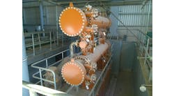
Identifying pump cavitation is challenging because most chemical industrial processes have a multitude of online instrumentation, valves, elbows, expansion joints, flanges, density meters, assorted probes and venturi tubes that impact performance. Now, add process liquids and precipitated solids that can cause scaling and corrosion, and a whole new investigation world for possible cavitation sources opens.
As liquids pass through piping, the inner surface acts like a brake causing the fluids closest to the sides to slow down via friction. This means the center flow is faster than the outermost flow, and this causes turbulence. And turbulence causes sine-like pressure waves to go with the flow. The faster the flow, the greater the turbulence and the greater the pressure waves.
When the turbulent flow and pressure waves reach restrictions in the piping, such as elbows, pressure drops cause bubbles to drop out of solution and head toward the pumps. Liquids and slurries tend to drop out solids either as actual solids or to come out as scale, not only on the inner pipe surfaces but also in flanges, elbows and other parts. These also act as flow restrictors causing turbulence by decreasing fluid velocities where they meet with increased flows through the centers of the pipes. This will also increase sine wave pressure drops.
Infrared cameras are an inexpensive tool that should be available to all operator shift teams in addition to maintenance personnel. Operators understand the equipment perhaps better than anyone else in the facility since they spend an entire shift working with it.
The cameras will show sediment build-up in doglegs of pipe galleries, where flows change direction, but the solids material in the stream may drop out. The image will also show the accumulation of solids in the bottom of tanks. This is especially important to note when solids shouldn’t be present anywhere in the system, or at least very little of it. Inside process piping, the liquids are under pressure and have a certain temperature, viscosity and density. If something changes in the process parameters, then dissolved solids may come out of solution and precipitate out. This is a red flag for scale formation inside the pipes feeding the tank and for pipe galleries ahead of pumps. (Figure 2)

Elbows are notorious sources of turbulence-causing bubbles that can reach the pump. They are the first places to check for internal sounds that don’t belong there. It’s rare to find a pure laminar flow through an elbow, let alone a pipe length. It could occur with very slow flows and a very viscous fluid, but otherwise it doesn’t exist under normal conditions. The one exception is adding undiluted polymers to the treatment of potable and industrial water. These can look like toothpaste being pushed out of a tube and end up in string-like globs. If an operator adds undiluted chemicals, such as polymers, to process systems at the injection point, they can hide or mask the amount and size of bubbles created at the system’s downstream locations. It only takes a moment to use the pen-to-ear method to listen to the noises coming from key elbows before pumps. (Figure 3)

Beyond Pumps: Other Cavitation Sources
Systems that have tank/pump/boiler combinations, such as glycol systems for heating downstream processes, create cavitation issues that are not always related to the pump. These systems rely on raised tanks to feed pumps pressure and gravity. An expansion tank above a glycol boiler is an example of system that creates bubbles at times that can create cavitation sounds that can be good way to illustrate various times be falsely attributed to the pumps. (Figure 4)
Figure 4 illustrates three operating snapshots of a glycol heating system. These pressure vessels usually have a blanket, such as natural gas, which can be entrained in the outlet flow. The top diagram in the set shows a system that is in balance with the pumps feeding the expansion tank — being in harmony with the liquid leaving it to feed the pumps below the vessel. The key factor enabling this balance is a float level control of the expansion tank.
The vessel feed pumps, which always use a variable frequency drive (VFD), speed up as the level of the expansion tank lowers. The pumps below the expansion tank are always running according to the set point of the downstream requirements and then draw from the expansion tank.
Although they are also VFDs, they are usually at a constant rate but can be set to react to downstream process requirements quickly. The expansion tank is so small in volume that even small fluctuations caused by level controllers that manage feed pumps can get out of sync with suction pumps when the downstream process starts to rock and roll.
Bubbles in the expansion tank form at the vessel outlet if the level controller is set too low before the feed VFDs speed up or of the feed VFDs are set to ramp up at slower rate than required.
The middle diagram of Figure 4 shows that at low tank level a vortex can form and cause gas entrapment of bubbles that then reach the pumps below creating cavitation sounds in them. The lower diagram of Figure 4 shows that a vortex didn’t form because the vessel level is too low. It may have been there at a slightly higher vessel level but dissipated when it reached a lower level. In this example, the small size of the expansion tank made it was very difficult for the process engineers to set all the in-and-out VFDs in sync with each other because of VFD card communication delays.
The lower diagram represents an actual situation I experienced when working as a senior lab tech at an oil company camp. It was a tough problem to troubleshoot because the head office, located 435 miles away, kept insisting the pumps were creating the cavitations. There were three pumps connected to a common header below the expansion tank that fed downstream parts of the process. A very simple fix for vortexing in expansion tanks that I suggested was to install baffles over the outlet at the bottom of the tank.
The entire system had to be purged to enter the expansion tank for a process engineer and myself to examine the actual as-built exit piping. We then fabricated a simple 2-foot-high baffle on four legs and installed it above the exit pipe. The baffle was slightly bigger than the pipe outlet and stopped all vortexing regardless of tank level. Baffles can work equally well for outlet pipes that are on sidewalls of a tank too. The idea of a baffle is simply to stop vortex formation.
Other Scenarios to Consider
The top diagram of Figure 5 shows a tank where the inflow doesn’t create any turbulence that can cause bubbles to enter the outlet pump. If the inflow is so harsh that it causes severe surface turbulence on the liquid surface, then the flow of the liquid to the outlet pipe supplying the pump can carry the bubbles to the pump. This illustrated in the middle diagram of Figure 5.
This liquid flow acts just like a Venturi and draws the bubbles with it. This can be caused if the tank is too small for the volume of liquids going through it or if the tank inlet pipe is too high above the surface of the liquid.
The bottom diagram of Figure 5 shows what can happen if the set point of the tank is too low before the feed pumps start up again or the VFDs are too slow to ramp up. Severe turbulence occurs. This is similar to the gurgling you hear when kitchen sinks start sucking air with the final volumes of dishwater.
Figure 6 illustrates more issues that can create cavitation in downstream pumps. The top diagram has a tank too large for the required flow if the level in the tank does not provide enough head pressure to force the liquid into the pump suction to satisfy the pump curve. Even though there may be no surface turbulence, the pump will cavitate due to feed starvation. This a big problem in many drinking-water treatment plants where tanks and pumps are below ground.
Pump starvation also can occur if the distance from the tank outlet to the pump inlet is too long, and the design engineers miscalculated on the diameter of the tank outlet pipe needed to meet the needs of the pump curve. I came across this issue a number of times in my career, especially in municipal water treatment plants.
The middle diagram of Figure 6 has a tank that controls inflow by level controllers and can have the same problem if the set point is so low that the pump inlet pipe gets starved and bubbles get sucked in. But in this case, the bubbles formed can be below the water surface, so they can be hidden from view.
The bottom diagram of Figure 6 has a non-pressurized tank supply pump that turns on and off due to level and also creates vortexes sucking in even more turbulence-created bubbles than simply poor head pressure. Anyone inspecting the pump vanes will likely see more damage than they expected. If they don’t properly identify the root cause, they could invest a lot of money on the wrong repair.
Experience Leads the Way
Troubleshooting pump cavitation problems can be easier than many textbooks indicate. It just takes experience. And a willingness to think outside the box. Yes, there are many times when the cause is due to the pump itself and pump performance curves not being met. It also can be related to other external factors causing pressure drops that lead to bubble formation.
But if time is spent upstream looking for piping sources for bubble formation, operations can drastically reduce the time, effort and money they spend to fix the problem.
The trick is to identify the true root causes of cavitation. In most cases, engineers who lack hands-on process operating experience present the greatest barrier to accurate identification of pump cavitation issues. They lack the time needed to learn the nuances of process noise. Experienced operators and very good troubleshooters can quickly identify the root causes and rule out commonly mistaken sources.