Piping systems are typically either originating from or ending at static equipment (often referred to as fixed equipment or fix equipment), such as vessels, tanks, towers, reactors, or drums. Nozzle connections to static equipment are recognized as critical points, subjected to high reaction loads and stress, often leading to failures and damage. These vulnerabilities are acknowledged as weak points in the equipment.
Ensuring the integrity of these connections involves three key aspects:
- The first is the effect of piping load on static equipment. Piping imposes loads on nozzle flanges and, consequently, on the equipment.
- Secondly, there is a less-known effect of static equipment or vessels imposing loads on piping due to factors like thermal movement, pressure or settlement.
- The third consideration is the flexibility of the vessel or static equipment, such as the nozzle and shell. This flexibility must be integrated into the combined equipment-piping system for an accurate analysis.
Here, we take a closer look at loads from static equipment to piping, shell flexibility, shell bulging and heat exchanger connections to gain a better understanding of the risk factors and preventive measures to ensure piping system integrity.
Loadings from Static Equipment to Piping
The most common load imposed by the vessel, or generally static equipment, to the connected piping is displacement of the vessel nozzle. The displacement can come from the thermal movement, the settlement of the vessel foundation, the movement caused by an earthquake, among others. It’s important to understand the thermal movement at each nozzle before conducting a stress analysis.
To calculate the thermal movement at the nozzles, first determine the fixed point from which the vessel expands or contracts.
A horizontal vessel usually includes two saddled supports. One of the supports is fixed, while the other can slide within slotted bolt holes, or similar. The fixed end is selected strategically, so the expansion or contraction of the vessel cancels a portion of the movement of the piping. This arrangement results in the minimum relative expansion or contraction, thus minimizing the forces and stresses.
For vertical vessels or vertical equipment, the equipment is usually fixed at the bottom or the surface of the foundation. The saddles, supports of the equipment in different shapes and forms, might have a different temperature from the equipment. This is oftentimes because the equipment, including the shell and head, is in direct contact with the process fluid, whereas the support or saddle is not.
To determine a more accurate fixing position, check the actual temperature distribution of the vessel (equipment) and saddle (support). After determining the fixed point, calculate the thermal movement at each nozzle. The interface with the vessel or equipment is usually the face of the nozzle flange. However, many stress simulations involve extending the piping to the nozzle-shell intersection. This extension serves the dual purpose of incorporating the flexibility of the nozzle neck and incorporating a portion of shell flexibility.
In situations where the temperature across the vessel shell is non-uniform, using an average rate of expansion or contraction is acceptable.
Shell Flexibility
The shell of a vessel or static equipment can have flexibility. But the inclusion of vessel flexibility in the piping analysis is still not universal. Some vessel engineers worry that the inclusion of shell flexibility will ultimately result in a stiffer piping system that might cause damage to the vessel.
This is partly true. However, the flexibility of the shell should be considered for a realistic overall flexibility and stress analysis.
At the same time, some margins should be considered to make sure vessel will not be under excessive deformations and stresses in extreme conditions.
Shell flexibility must be factor in to the analysis, or it will not be accurate. On one hand, the piping is finalized by piping engineers who consider the shell as rigid. On the other, the piping load is evaluated by vessel engineers who consider the shell as flexible. This type of double-standard approach results in a very low allowable piping load for a thinner vessel wall, whose flexible nature cannot be counted in such a stress analysis. Treating the vessel connection as rigid, although conservative for thermal expansion or contraction analysis, can result in a very expensive combined system. Sometimes the system can also become improper or unsuitable from other aspects such as dynamic excitations or occasional load environment.
By treating the shell connection as rigid, the bending moment at the shell nozzle can be at least 10 times as high as the one calculated by including shell flexibility. If shell flexibility is not included, the resulting artificially high piping forces and moments may require a very flexible piping, such as the one using a very large expansion loop, or even an expansion joint, to reduce the nozzle reaction loads within acceptable limits. Such piping, resulting from the rigid connection assumption, is not only expensive, but also becomes a potential source of operational problems such as vibrations.
For instance, the loop is prone to vibration and is more likely to suffer from damage due to earthquakes and other occasional loads. Proper inclusion of shell flexibility in the stress analysis is not only economical and accurate but also more reliable and safer. Most systems would have the piping forces and moments increased by two or three times when the connections are considered rigid, as compared with that calculated with realistic flexible connections. Among the six degrees of freedom at a vessel connection, the flexibilities in the directions of two bending moments and the direct axial force are considered significant. A good recommendation is to simulate piping and static equipment in the same stress model and let them to interact. At the same time, consider suitable safety factors. This is a realistic and accurate method of stress analysis.
Connections Affected by Shell Bulging
The tank connections located at the lower end of the tank cannot be treated in the same manner as ordinary vessel connections due to some associated unique characteristics. Tank connections, which are located within a relatively short distance from the tank bottom, can generate considerable rotations and movements to the connected piping due to the bulging of the tank shell under the hydrostatic pressure of the liquid contained.
This is often referred to as low-type tank connections. The surrounding of the connection is also much more complex than that of an ordinary vessel connection. Therefore, the flexibility of these low-type tank connections can’t be readily estimated from the vessel connection methods. The displacement and rotation of the tank shell have created some known problems and should be handled with care. This can also be applicable to some other special vessels such as some towers, etc where such effects exist.
A set of unique approaches is needed to handle the interaction between the tank and the piping. A good method is one in an appendix of API-650, “Allowable External Loads on Tank Shell Openings.”
In general, there are two sources of shell displacements. One is the thermal movement of the tank shell, and the other is the diametrical elongation due to pressure from the liquid head. The rotation occurs only at the low-type connections. The rotation is produced by the choking of the tank bottom. Because the tank is simply resting on the foundation, the rotational resistance is small.
Heat Exchanger Connections
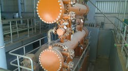
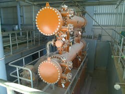
Heat exchanger connections are similar to vessel connections. But they deviate from ordinary vessel connections in two ways. One is that the heat exchanger shell is generally small compared to an ordinal vessel. Therefore, they behave more like a pipe rather than a vessel. The other deviation is that for a heat exchanger, the manufacturer will normally specify the allowable piping loads that the heat exchanger nozzle can sustain. The piping engineer should ensure that the piping load on the nozzle is within the allowable limits.
It’s also possible to model a heat exchanger as a pipe and include it in the piping stress analysis. However, because of the way it is usually formulated, the stress analysis with such a model, including the heat exchanger directly as a pipe element, can only viewed as an indication. The only reliable reference is the allowable load given by the manufacturer.


