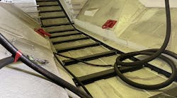
Many chemical makers overlook chain conveyors. That’s not surprising because published information on them is sparse. Yet, these strong and rugged conveyors ideally suit applications such as special feeding units that call for slower transportation speeds over short distances and at moderate inclines. The angle of incline can exceed that usually used for belt or other conventional conveyors — even steep and varying angles are possible. Chain conveyors generally operate at relatively high discharge rates in applications that need great flexibility and pose load variations.
The devices usually have a lower profile and lighter design than other conveyors and, thus, offer benefits in applications with limited space or requiring a compact/low-weight unit. Moreover, chain conveyors often operate better with sticky materials and in challenging services than other conveyors such as rubber belts (which tend to retain sticky materials that even multiple cleaning stations might not effectively remove).
A chain conveyor consists of a trough or bed (bottom of the conveyor casing) on which run continuously driven chain(s) with pendants, flights or attachments. These pendants, flights or attachments scrape the bulk material over the trough, moving solids forward to the discharge point. The chain is driven via sprockets (wheel teeth).
The chain is specifically designed for conveyor service. It usually consists of a series of journal bearings held together by link plates or something similar. Many design alternatives exist. In a popular one, each bearing comprises a pin and a bush on which the chain roller revolves. Commonly, drop-forged chain, also known as scraper chain, is used. Other options include hollow-bearing-pin, solid-bearing-pin, deep-link, forked, round-link and box-scraper chain.
Attachments are fitted to a conveyor chain to adapt it for a particular application. Each attachment typically is made from single piece of steel.
Many different variations of chain conveyors are possible, depending on type of chain, attachment details, and their configuration. In one model, known as a pitch ladder chain conveyor, two side chains move ladder-type attachments. Another model, the pitch loader chain conveyor, features a centrally located chain and extended attachments to both sides.
Each type of conveyor chain comes in a range of pitches. The need for adequate wheel tooth strength usually dictates minimum pitch while the rigidity of chain plate determines the maximum. Strengthening the chain with bushes between the link plates (or other means) may enable exceeding the maximum pitch so long as there’s still enough clearance with the sprocket.
As a very rough indication, chain conveyor width typically ranges from 0.2 m to 1.5 m and length runs from a few meters to 30 m.
Drivers And Tension Control
Electric motors (usually with gear units to convert the speed) or hydraulic motors drive the sprockets. Most sprockets are made from special grades of steel. The sprockets typically have an odd number of teeth (preferably a prime number), although a composite or an even number sometimes is used. Modern sprockets are specially designed to spread the load across more teeth (at least three), ensuring maximum contact surface between the chain links and the sprocket teeth during operation. This results in lower wear and extended life of the sprocket and the chain. Sprockets in double pitch configuration also are available. Double sprockets offer larger pin/journal area, greater pull strength and increased bearing area. They wear evenly and offer a longer service life and lower noise than standard sprockets. They often find use in critical and high reliability services.
Chain conveyors require overload protection; different means and devices can provide this. A simple solution often is to use shear-pin sprockets that break when overloaded, stopping the chain conveyor and saving considerable expense and downtime. Another option is to measure the slip of each gear unit; a chain stall then triggers the switching off of drivers. Alternatively, clutch(es) can be used, with a suitable control unit opening them when required. You can employ two or more methods simultaneously to increase overall reliability and safety.
Suitable chain tensioning and tension control is extremely important. Tension should be adequate for proper operation — and adjustable. Wear increases if chain adjustment is too tight or too loose, allowing chain to flog.
Construction Materials
High-quality chain conveyors usually use specially selected high-strength low-alloy steels that can withstand abrasion and other wear as well as corrosion. Correct heat treatment nearly always is necessary for good characteristics and optimum wear resistance. (Chain conveyors manufactured from plastic and non-metallic parts do find use in small and limited applications.)
Wear is a major concern for chain conveyors. Achieving optimum wear life requires consideration of many different aspects such as the selection of material, drive arrangements, the speed, etc. Long-lasting chain with case-hardened pins and large bearing area in journals reduces wear.
Special coatings for steel parts such as urethane coatings — if compatible with the service — can reduce wear, noise and metal-to-metal friction. Before opting for such a coating, check prior applications and seek successful long-term operating references.
Correct lubrication of the chain’s bearing surfaces will minimize power absorption, wear rate, erosion, corrosion and noise. For normal conditions and operating temperatures, a quality mineral oil with medium viscosity may suffice. Self-lubricating chains that require no additional lubrication are available for certain applications.
There is a link between smooth and low-noise operation and system reliability and long life. The key is to prevent excessive metal/metal friction and damage mechanisms. These adverse effects can create noises, inefficiencies and reliability issues. Not surprisingly, the most productive and reliable chain conveyors also are the quietest, smoothest and longest-lasting ones.
A useful concept for ease of maintenance of large, critical chain conveyors is separation of wear and structural parts. This enables easily replacing the very hard materials used for wear parts while making the structural parts of high-strength steel expected to last for many years.
Operating Issues
Many different parameters — such as the details and layout of the chain conveyor, the chain speed, involved frictional coefficients, details of bulk materials (particle size, etc.) and others — affect efficiency and performance.
The chain’s speed is a major parameter; mass flowrate changes significantly with variation of chain speed. Frictional coefficients involved also are important; they can affect mass flowrate, consumed power, and wear of parts.
The average wear depth depends on operating parameters, the chain speed and the characteristics of the bulk material (such as its particle size, abrasiveness, etc.). Higher chain speed and larger particles often lead to more wear of various components. However, the relationship between the speed and wear is highly nonlinear and complicated.
Some chain conveyors have generated high noise that could lead to permanent hearing loss. This noise stems from the interaction between different moving parts (conveyor flight components) and fixed parts. Traditionally, the most important noise control measure has been the application of proper coatings (such as urethanes).
Areas where impacts and heavy friction occur, such as where the chain changes direction at the discharge end, require careful consideration during design, manufacture and installation. Such impacts, heavy friction, etc., often result in excessive noise, high maintenance and low reliability.
Material being handled may suppress noise caused by the chain conveyor system by dampening impacts that occur between the conveyor flight parts, conveyor trough/deck, etc. Therefore, the noise during empty or low-load operation often exceeds that of full-load operation.
Sometimes, resonance has occurred between chain system and trough assembly. This resonance not only undermined the smooth operation of the chain conveyor system but also became the main cause of noise generation and damage. Therefore, a critical chain conveyor requires a full vibrational study. Such a study also would help to improve overall structure and reduce stresses and deflections.
Wear And Reliability
The metal parts in chain conveyors are prone to wear and tear in long-term operation. The damage and degradation mechanisms depend upon the nature of the particular part. The life and reliability of a chain conveyor is determined not only by these damage and degradation mechanisms (pitch elongation, etc.) but also by the wear of each component part and the weakest link in the system. So, thorough periodical inspections and ongoing condition monitoring always make sense.
Mutual friction between different parts such as outer link plates and inner link plates creates wear. When the amount of wear exceeds 25–30% of the thickness of the original part (link plate, etc.), the strength of the chain decreases considerably. So, ideally, replacement should occur before parts reach this degraded stage.
In many configurations, the chain is installed and moved on a conveyor trough (deck or bed — Figure 1); this trough/surface is prone to wear by both the chain and the bulk materials handled. The wear mainly concentrates around the chain unless delivered materials are significantly abrasive. Wear of the accelerating area is more serious than that of the stable (constant speed) area.
Pin wear generally occurs when chain engages with sprocket teeth and each link articulates around the sprocket. Bush wear arises when it contacts the track and the load is supported by the pin and bush. It also can occur when contacting the sprocket tooth. Chain usually should be replaced when the bush has worn through to the pin.
Because sprockets are under considerable loads, stresses and continuous/repetitive contacts, they often suffer wear and damage. When a sprocket is worn out, chain clings to it and tends to cause a vibration when coming out of the sprocket. While giving a general value for allowable wear of sprocket is difficult, as a very rough indication, don’t allow the wear to exceed 2.5-mm depth.
Degradation
Elongation of chain pitch is a common degradation mechanism. It usually occurs when the chain engages with the sprocket or runs along the track. The flexing of the chain around the sprocket causes wear between the pin and bush, thus allowing the pitch to stretch. As this stretch increases and the pitch become longer, the chain tends to climb the sprocket tooth. To check the pitch, take the average of measurements of 10–20 pitches under operating tension. Then, calculate the elongation by comparing the original pitch when new against the measured pitch of the worn chain. As rough general guide, replace the chain when pitch elongation approaches the limit of about 103–105% of the original pitch.
The wear mechanism of the trough (bed or deck) under the chain and moving materials usually is micro-cutting. This mainly relates to abrasive conditions. Such a complex wear process also may involve corrosion depending on the type and characteristics of the bulk materials. In challenging services, the wear mechanisms mainly have been micro-cutting and corrosive wear accompanied by fatigue fracture.


