The most-common technologies for liquid level measurement use either a differential pressure reading or a displacer with a buoyant force to infer liquid level. In both cases, the device must see into the vessel via level taps or nozzles. Vessel fabrication requirements can restrict the placement of such taps. A recent case of specifying a horizontal separator highlights one of these limits.
That vessel could accumulate liquid condensate from a gas system. Nominally, the vapor was liquid free. Nevertheless, due to upstream upsets, heat loss or other operating conditions, small amounts of liquid could collect; the liquid rate was assumed to be very low.
The plant operators would inspect a local level indicator on a schedule and then drain the vessel to a closed system as needed. Ideally, only a little liquid would accumulate, so a very small capacity drain system would suffice.
The facility wanted the level instrument to show even the first small amount of liquid. This would ease troubleshooting and detecting upstream upsets. Dead volumes would make identifying the shift in which an upset occurred more difficult.
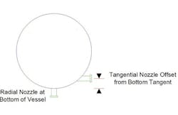
Figure 1. Two options for the lowest level tap are a nozzle on the side offset from the tangent or a nozzle right on the bottom.
Figure 1 shows a cross section of the horizontal vessel. Ideally, the level instrument would use a tap on the side of the vessel tangent to the bottom and a higher liquid tap. However, as Figure 1 indicates, the lower level tap is offset. Rather than being aligned with the bottom of the vessel, the nozzle instead is a distance above.
A nozzle exactly on the vessel tangent can pose two mechanical issues, one for the vessel and the other for the nozzle.
Installing an exact tangential nozzle is much more complicated than putting in a nozzle elsewhere along the vessel. It demands relatively long welds and special construction. This is particularly true for small vessels. Moving the nozzle up slightly, off the tangent line, makes vessel fabrication easier and cheaper.
Also, a nozzle exactly tangential to the vessel requires a long horizontal distance to add space between the vessel wall and the side of the nozzle flanges. Shifting the nozzle away from the tangent puts the nozzle in a location where the curve of the vessel moves away from the nozzle flange; this makes the nozzle shorter.
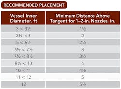
Table 1 lists recommended minimum distances off the tangent for different vessel diameters. As the vessel gets larger, the unmeasured space below the lower nozzle can become large.
Table 1. Appropriate distance increases as vessel diameter goes up.
An alternative configuration (also shown in Figure 1) puts the lower nozzle on the bottom of the vessel. This eliminates the problem of the dead volume. However, it also makes the nozzle susceptible to blockage from sediment, scale or debris that falls to the bottom of the vessel.
While differential pressure cells can work with nearly any nozzle configuration, displacers usually function best with an external level well added. The external level well opens up the possibility of using other technologies, such as mechanical and magnetic float ones, as well.
In all cases, sensible equipment specification requires taking things such as nozzle minimum clearances into account. Equipment specification must consider not just process needs but also mechanical and cost constraints. The wise engineer understands both the process and the mechanical requirements. In this particular case, the need to measure levels close to the vessel bottom may conflict with mechanical requirements of keeping a minimum offset for the nozzles.
Eventually, we opted to use a nozzle attached to the bottom of the vessel because this would provide the most reliable reading of low liquid levels.


