A survey of more than 500 individuals involved in process engineering, procurement, operations and maintenance at over 200 plants worldwide identified “oversizing” as the number one control valve problem. In a few instances, oversizing is intentional (e.g., to prepare for future production rate increases). However, in most cases, oversizing results from well-meaning but misguided decisions during the valve selection process. Unfortunately, an oversized valve can incur a sizable economic penalty and cause significant operating problems. So, let’s look at how to avoid oversizing.
REASONS FOR CONCERN
At full operating conditions, control loops operate over a very narrow, essentially steady-state throttling range where small input signal changes to the control valve result in small valve stem or shaft movements. As you might expect, a small position change by a valve that’s oversized gives a larger-than-desired change in flow. Depending upon the accuracy of the elements in the loop, the control system then responds to correct the situation, which can result in a throttling sequence that oscillates back and forth, causing continuous variation in process conditions.
While a higher-performance digital valve controller can mask this “dithering” by the control valve to give the appearance of acceptable loop performance, oversizing problems remain. In fact, an incorrectly sized control valve can result in problems even though the plant appears to be running smoothly.
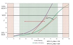
Figure 1. Oversized valve (NPS 4) can’t provide adequate performance.
During a system startup or a turndown to 25% maximum continuous rating (MCR), operating conditions will fall outside of the oversized valve’s ability to adequately control because of the need for extremely small valve movements. Process control in this range may be near impossible depending upon the inherent flow characteristic of the valve. High gain characteristics (i.e., the amount of change divided by the amount of input) can result in instability, again causing the valve to cycle.In addition, these off-case, low-flow conditions can lead to valve throttling occurring essentially right at the seat or seal. The resultant high-velocity flow across the narrow opening causes wear and erosion. Impingement of the accelerated process media can cut lines into sealing surfaces, an effect that reduces the control element’s ability to prevent or minimize leakage when the valve closes. Erosion to the contour of the valve’s flow-control element alters its flow characteristic and ability to control as intended. More severe cases can prompt vibration that causes additional damage and, ultimately, equipment failure. A valve gives the best control when it’s sized to operate around 60%–80% open at maximum required flow and not less than 20% open at minimum required flow. Using a larger-than-necessary valve compromises performance, as indicated in Figure 1, which compares flow coefficient, Cv, versus travel for Nominal Pipe Size (NPS) 4 and NPS 3 valves for a service needing an NPS 3 valve.Because of their compromised rangeability, improperly sized control valves also can cause problems during process transients. A typical control valve with an equal-percentage flow characteristic has about a 30:1 turndown ratio (i.e., the ratio of maximum Cv to minimum Cv). However, when the valve is oversized and throttling at the low end, its turndown ratio falls to 3:1 or less.Also, installing too large a valve amplifies mechanical problems such as stiction and hysteresis, making the system difficult to control and potentially causing process upsets.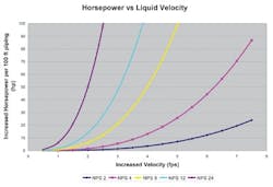
Figure 2. An oversized valve requires a dramatic increase in compressor or pump horsepower.
Oversizing of control valves has a domino effect. Safety relief valves must be sized to match the capacity of the control valve. Within a bypass configuration, isolation valves, bypass valves and drain valves all must be larger, which can impact the size of piping and structural pipeline supports.
Consider also that to achieve or maintain flow velocity in a loop equipped with an oversized valve requires a dramatic increase in compressor or pump horsepower (Figure 2). Sizing issues can propagate beyond erection costs into perpetual operational cost increases as pumping horsepower increases by a power of three to maintain the desired fluid velocity within the piping.
SOLVING THE VALVE-SIZING PUZZLE
When trying to avoid — or correct — valve-sizing problems, it’s important to understand the causes of valve-sizing errors. Emerson research has identified several major contributors: multiple safety factors, selecting line-size valves, and out-of-date process data resulting from changes in process conditions or conditions that differ from the original design.
To correct systems with improperly sized equipment, it’s vital to obtain accurate process data at all expected operating conditions. Then, size the valve to perform optimally at these conditions.
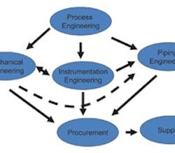
Multiple engineering disciplines impact valve sizing, with each contributing their specialized flow-control know-how to valve selection.
For example, process engineers determine the fluid flow rates, temperatures and pressures that must be established and then maintained based on the feedstock being handled and the desired system output.
Their goal is to maximize output with minimum input and, to do so, they design the process for a 100% MCR.
They also develop control strategies for process turndown and turnup scenarios as well as those to be encountered at startup and shutdown, taking into consideration fluid flow rates and process conditions.
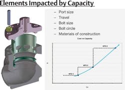
Figure 3. A decision to add “a little more margin” often will hit equipment limits, forcing a step-change in size and cost.
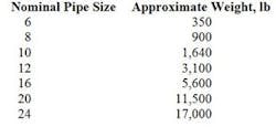
Table 1. Going up a valve size incurs a substantial penalty in weight.
The instrument engineers not only establish equipment requirements and specifications for normal system operation but also size equipment for worst-case scenarios. They may add extra safety factors at this point — so you can begin to see how flow control and measuring equipment starts to become “oversize” for the task at hand. It’s critical that instrument engineers communicate with process and piping engineers to ensure that valves, meters and controllers not only meet but also, importantly, don’t exceed system flow and pressure-drop requirements.Valve supplier application engineers convert process control requirements into detailed equipment specifications that lead to determining the right valve for the job. The application engineer must ensure the valve operates within reasonable throttling limits, being able to pass the required flow rates. Borderline applications almost always are pushed into the next larger size, resulting in a significant step-change in equipment cost (Figure 3).For example, when an NPS 6 valve can meet a design’s expected process flow requirements but oversizing by the plant’s engineers push the parameters past that valve’s capacity, forcing a move to an NPS 8, then cost takes a significant jump upward (Table 2).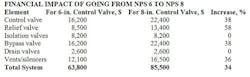
Table 2. Increasing the control valve size leads to a number of other changes that raise total cost.
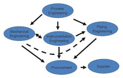
Figure 4. Close collaboration among the design groups and the supplier is needed to optimize system components and minimize unintentional equipment over-specification.
MICHAEL MCCARTY is vice president of the Fisher Sliding Stem and Baumann Valves Business Unit of Emerson Process Management, Marshalltown, Iowa. E-mail him at [email protected].