Centrifugal pump systems with flow throttled by a control valve are ubiquitous at process plants. Unfortunately, the majority of pumps are oversized, which both poses problems regarding controllability [1] and wastes energy.
Pump oversizing occurs for two major reasons. First, a system’s pressure drop must be calculated rather early in planning using estimates for pipework and its fittings. Unfortunately, values taken from the literature, for example of flow resistance coefficients of valves, may vary widely. Consequently, dynamic pressure losses are somewhat shaky. Static pressure differences usually are better defined. Hence, planning engineers must add some safety margins. Correcting a pressure drop calculation much later when pipework has been designed does not really solve this problem. Some margin also might be added to the rated flow. Second, the pump’s manufacturer adds safety margins, too, to ensure the pump meets guaranteed performance, in particular if the liquid handled is not water. So, it is nearly impossible to avoid installation of oversized pumps. Hence, the only realistic option is to adjust a pump based on experience once the plant is operating.
The vast majority of pumps in the process industries are centrifugal radial ones, mostly of moderate power consumption. For example, a 2010 survey of around 30,000 pumps by the Fraunhofer Institute in Germany revealed that about three-quarters require less than 15 kW and that most of these have installed spares. A centrifugal pump can be adjusted to some extent to a changed operating duty point by trimming its impeller’s diameter. Manufacturers use this method to achieve the operating point needed by the customer; it also might be appropriate later whenever necessary. In multistage pumps, a plain disk could replace an impeller.
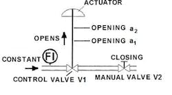
Figure 1. Maintaining a constant flow rate while adjusting the manual valve enables determination of opening a2.
Necessary Calculation
Taking advantage of impeller trimming in an installed pump requires calculating in some way the pressure difference that could be avoided — to yield a revised operation duty point. For a system with parallel branches, the control valve, of course, must be located in the flow path that determines the pressure drop of the system. Because, in a system with an oversized pump, the control valve tends to close more than originally assumed, its pressure drop exceeds the one originally defined. This excessive and thus avoidable pressure difference, Dp, can be calculated, provided flow rate, QD, and valve’s opening, a1, are known:
Dp = G×QD{[1/Cv(a1)]² - [1/Cv(a2)]²} (1)
This then allows calculating the equivalent pressure height, ∆HL, which is preferred when it comes to centrifugal pumps’ curves:
∆HL = Dp/(g×G) (2)
Cv is the valve flow coefficient, g the gravitational constant and G the density; QD should represent the highest flow rate encountered in operating the system, i.e., the plant running at maximum rate. The Cv value depends on the valve’s opening or travel. For a given opening, it either may be found from the supplier’s data reflecting Cv for non-choking flow or calculated via the Cv–capacity relationship, the valve’s flow characteristic function and opening a. In Eq. 1, a1 refers to the opening of the excessively throttled valve. Opening a2 refers to a reference value. Travel a1 can be read in the field or may be recorded or registered by a position transmitter in the control room.
When designing a plant, the traditional method to size a control valve consists of allocating to it 25–50% of the dynamic pressure drop of the corresponding flow path or, alternatively, an absolute pressure drop; its opening is fixed to, say, between 60% and 75%. This original design opening constitutes a2 and thus allows calculating ∆HL; also the original pressure drop may be used directly. Nevertheless, to determine the maximum avoidable pressure loss — and thus maximum potential energy savings —the control valve should be as wide open as possible while still achieving good controllability. The value of opening a2 can be found by using the configuration shown in Figure 1,while maintaining a constant flow rate (monitored, e.g., by a clamp-on flow meter)and applying the following procedure: Throttle manual valve V2; the control valve V1 will open to compensate for the reduced pressure at its outlet port. (In other words, the pressure loss of control valve V1 shifts partially to valve V2 and, as long as the flow rate does not decrease, the sum of the pressure losses of V1 and V2 remains constant, i.e., the operating duty point does not change.)Repeat this procedure several times in the field until controllability deteriorates. Select the opening just before this happens asa2 [2].
Figure 2. Deducting the avoidable pressure loss defines the position of R, which affects the diameter of the trimmed impeller.
An H-Q diagram (Figure 2) provides a clearer picture. Here, D reflects the original operating duty point at design flow rate QD, and HP the original pump curve of the oversized pump. R indicates a hypothetical duty point determined by subtracting the avoidable pressure loss, ∆HL, calculated via Eq. 2. Hence, R can be used to define the diameter of the trimmed impeller, which either is inferred from manufacturer’s data or found by applying a method that is well known from the literature [3]. In some cases, installing a new pump might be preferable. The pump curve satisfying R is marked HP,R. Deleting the 2nd term containing a2 in Eq.1 yields the absolute pressure drop the control valve exerts; this is the pressure loss avoidable through replacing a throttling valve assembly as final control element by a pump with a variable speed drive.
Plant managers may have some reservations about operating a less powerful pump having a trimmed impeller. Having an installed spare pump with the original size impeller, as often is the case, should alleviate these concerns.
Performing the task of modifying a pump in an existing facility demands cooperation from the plant’s operations staff and instrument and maintenance engineers as well as from process specialists. Coordinated teamwork is crucial.
WALTER SHICKETANZ is a consultant based in Rosenheim, Germany. E-mail him at [email protected].
REFERENCES
1. McCarty, M., “Properly Size Control Valves,” pp. 21–25, Chemical Processing, January 2015
2.Schicketanz, W.,“Reducing Avoidable Pressure Loss,” pp. 18–21, World Pumps, January 2011.
3.Hydraulic Institute, “Trimming or Replacing Impellers on Oversized Pumps,” pp. 38–39, World Pumps, April 2009.


