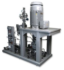
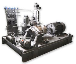
Centrifugal pumps usually handle most liquid pumping services at plants. Indeed, the pumps, which come in vertical and horizontal configurations (Figures 1 and 2), are ubiquitous at most sites. However, such pumps do not suit highly viscous liquids; these liquids require positive displacement pumps. Unfortunately, some engineers still specify positive displacement pumps for many water services and some medium viscosity liquids in the hope of, say, greater flexibility or operational advantages. In most such cases, though, variable-speed centrifugal pumps are better choices.
Figure 1. This high-speed centrifugal pump conforms to the API-610 standard and is driven by an electric motor through a gear unit. Source: Sundyne.
Ordinary centrifugal pumps usually can tolerate solids’ levels up to around 7% — with appropriate corrections on the pump curves. Specially designed centrifugal pumps can handle up to about 15% solids. For levels exceeding approximately 20%, specially designed positive displacement pumps, such as screw pumps, often are preferable.
These are rough guidelines. Pump selection depends upon many factors including the specifics of the service.
[javascriptSnippet ]
If you opt for a centrifugal pump, a key to achieving optimum performance and reliability is to operate the pump as close as possible to its best efficiency point (BEP), which is its most stable and suitable operating point. The pump’s hydrodynamic unbalanced load usually is at its minimum at the BEP. If the pump operates at points far from the BEP, the resultant increased hydrodynamic unbalanced load can affect performance and reliability. This unbalanced load usually is at a peak at the shutoff point. So, avoid long-term operation near the shutoff point.
It’s sensible to target a relatively narrow operating range around the BEP. While the exact range depends upon the pump hydraulic design and the application, a good target for typical services often is to operate the pump within the range of 85%–107% of the BEP. Unfortunately, this ideal target frequently is not viable; so, select an optimized operating point (or operating range) that suits the service.
An important capacity-restricting factor could be the net positive suction head (NPSH) requirement. This is because a flow significantly greater than the BEP flow may increase pressure drop (within the suction passages and the suction piping) to a level above the NPSH margin, resulting in cavitation and pump damage.
Component wear and deterioration can open up pump clearances and cause a significant increase in liquid recirculation compared to new/healthy pumps. Liquid recirculation is one of the most important factors for pump efficiency. (For more on recirculation, see: “Fight Flow Recirculation.")
Operational Considerations
For a pump in a closed-loop service such as a recycle application, the operating point should be very close to the BEP or a little (say, around 5–10%) to the left of the BEP. Unfortunately, users often pay inadequate attention to the curve details of a pump for a closed-loop recycle service, sometimes even failing to check alternative operating points or recycle flow ranges on the pump curve. For some recycle services, the flow is fairly constant most of the time and the operating point won’t move much. However, in other applications, the recycle flow varies significantly — this requires locating and evaluating all possible operating points on the pump curve.
Figure 2. This baseplate-mounted heavy-duty API-610 pump has an electric motor driver and a gear unit. Source: Sundyne.
Many pump applications are known as batch transfer services. In these, pumps connect to vessels, tanks or other equipment with variable liquid levels and operate with varying liquid loads to fill the equipment (via the pump’s discharge) or empty it (via the pump’s suction). Such systems often include control valves. The operation of these control valves can alter the differential pressure significantly. In these services, the pump head constantly varies — sometimes at rate high enough to cause a sudden change in pump operation.
Batch transfer services can have two sets of extreme operating points, one for the highest head (highest differential pressure) and the other for the lowest head (lowest differential pressure). The usual problem with pumps for batch transfer applications is that the pump is chosen based on matching the operating point for the highest head with the BEP, forgetting the other head requirements, particularly the lowest head operating case. Because of this, the selected pump most of the time will operate to the right of the BEP (sometimes far from the BEP), which takes a toll on reliability and efficiency. This wrong pump selection will result in larger pump than required, higher power consumption, lower efficiency, more vibration/noise, shorter seal/bearing life and less reliability than that of a correctly sized pump. In other words, the error will cause significantly higher capital expenditures as well as higher operating costs due to unscheduled shutdowns, reliability issues, etc.
To select the correct pump for a batch transfer service, you must consider the operating point of the highest head at the left of the BEP and the operating point of the lowest head at the right of the BEP and then evaluate how to achieve best overall operation. This requires very carefully locating the operating points on the pump curve, considering details such as the efficiency, the NPSH required and many others. Usually, it’s best to choose a pump that operates most of the time near the BEP. As an indication, the mid-point (the operating point between the highest head and the lowest head) typically should fall near the BEP.
A mid-point a little to the left of the BEP results in a slightly smaller pump; it could be a good option if the pump is expected to operate more of the time at (relatively) low-head operating points. This sometimes is preferred because the operating margin could be more on the left side of the BEP (usually to 85% or even 75% of the BEP flow). Conversely, a mid-point a little to the right of the BEP, necessitating a slightly larger pump, could be a good option if the pump is expected to operate more of the time at (relatively) high-head operating points. In some cases, it also is favored to provide additional power and pumping capability to deal with unexpected conditions or a tendency for higher head cases.
Generally, you should identify all possible operating points and evaluate pump operation for all of them. It’s also important to consider operating points on the pump curve when the pump is (slightly) degraded. For some pump applications, such as batch transfer services with great differences between the highest and the lowest head points, a variable speed centrifugal pump often makes sense.
Pump recycle line. When a centrifugal pump (particularly a small one) must run at different operating points, consider recycling a portion of pumped liquid to achieve these different operating points. In this way, the pump can continue to operate efficiently and reliably at its BEP. Such recycling can improve pump reliability at the expense of a modest increase in power use, which could be insignificant for a small pump. Do not connect the recycle line to the suction line; this can cause turbulence at the suction of the pump, which could result in pump operating problems or even damage. Instead, pipe the recycled liquid back to the suction source (for example, a suction vessel or a suction tank), returning it at a point that causes the minimum turbulence. Route the recycled liquid to the other side of the suction tank (or suction vessel/reservoir) than that of the suction intake point. Often, a suitable baffling plate arrangement or other design can ensure turbulence-free recycling.
Parallel operation. Sometimes, pumps must operate in parallel. For instance, in some high flow applications, the largest pump available may not suffice on its own. In other services, the necessary operating flow range is too wide for a single pump to economically handle. Good examples are some high flow and high power services that require operation in the range of around 20%–100% of the total flow. For these services, because the power rating is high, recycling or operating a pump far from the BEP can result in significant power waste (and, sometimes, reliability issues).
When pumps operate in parallel, each will handle a lower flow rate than when operated alone. In other words, for two identical pumps in parallel, the total flow is less than two times each pump’s flow. Always use the minimum number of pumps; whenever possible opt for two pumps over three or more.
Parallel pump operation raises other issues and risks:
• The pump (head flow) curves of the pumps should be similar (say, within 2–3% tolerances).
• The combined pump (head flow) curve usually is (relatively) flat, which can make the system more vulnerable to unstable operation.
Pumps operating in parallel require careful selection and precise operation/monitoring. (For more on issues related to parallel pumps, see: “Keep Parallel Pumps in Line,” http://goo.gl/YviVCO.)
High vibration. Excessive noise and vibration could stem from cavitation, internal recirculation or air entrainment. High vibration can extensively damage seals and bearings.
Suction recirculation is the simple name for various complex hydrodynamic issues that can arise from low flow. Some suction recirculation issues are turbulence-type problems or originate from swirling actions. Some centrifugal pumps can resist suction-recirculation-type instabilities until flow becomes quite low, sometimes as low as 35% of the BEP flow. Other pumps suffer from suction recirculation even at around 70% of the BEP flow. Suction recirculation can result in some damage and pitting, usually at around halfway along the pump impeller vanes.
Discharge recirculation is a hydrodynamic instability that also arises at a low flow. The issue usually stems from unsuitable design of pump components or, sometimes, from inappropriate clearances (particularly at the discharge side of impellers or the impeller/casing clearance). The damage and pitting resulting from discharge recirculation could occur at the pump impellers’ discharge ports.
The liquid supplied to a pump may contain some entrained air or gas (i.e., vapor bubbles), which can result in instability similar to cavitation. The air/gas entrainment or cavitation usually causes pitting and damage at the eye of the pump impeller. The noise and vibration stemming from entrainment or cavitation may resemble that from other malfunctions — but a pump inspection and, particularly, the location of the pitting or damage on the pump impeller usually can pinpoint the root-cause of the issue. Gas entrainment commonly occurs when pumping a liquid that is close to its boiling point or because of complex or inappropriate suction piping (or general design of the suction system) that encourages turbulence.
AMIN ALMASI is a rotating equipment consultant based in Sydney, Australia. E-mail him at [email protected].


