In an integrally geared centrifugal compressor (IGCC), several pinion shafts are arranged around a large central bull gear. An impeller (usually a 3D semi-open one) can be mounted on each end of a pinion shaft. Currently, machines with up to 10 impellers (5 pinions) are available. The compressor shafts can run at high rotational speeds — up to 75,000 rpm. The bull gear generally is driven by an electric motor, which can be a conventional 1,500–1,800-rpm unit or a high-speed 3,000–3,600-rpm one.
In contrast to conventional centrifugal compressors in which all impellers run at the same speed, in IGCCs each pinion can run at a different speed. Thus, every impeller pair can operate at its optimum aerodynamics speed. This is an important advantage — particularly for gases with medium or high molecular weights — that results in higher efficiencies than those of conventional compressor designs.
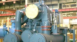
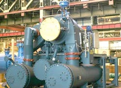
A multistage IGCC (Figure 1) usually is designed so each stage shares the work equally, i.e., each impeller passes the same mass flow at almost the same compression ratio. For example, in a 6-impeller compressor with a total pressure ratio of around 30, the compression ratio per 3D semi-open impeller would be around the sixth root of 30 (or about 1.76) more or less.
Figure 1. Each stage typically handles an equal amount of work. Source: Siemens.
Design Issues
The 3D semi-open impellers generate relatively large aerodynamic exciting forces. These forces can cause high-speed shafts and the whole machine to vibrate, and also could induce dynamic stresses. IGCCs produce more vibration than conventional centrifugal units, which contributes to their relatively less reliable and noisier operation. Evaluating the dynamic stresses and vibrational behavior of an IGCC requires consideration of all exciting forces from impellers and complex gear systems.
Another important consideration is the operation of these complex machines at part-load or alternative operating conditions. The aerodynamic exciting forces in 3D semi-open impellers and the complex gear unit behaviors differ in such situations. Part-loads often create the worst cases of dynamic loadings for many gear systems. The behavior of any rotor varies significantly as the tangential force produced in the gear changes with operating conditions. Therefore, analyzing the dynamic loads and the vibration of different parts of these machines (particularly pinion shafts) at part-loads is important.
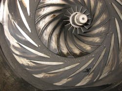
To increase the capacity of the 3D semi-open impeller (Figure 2), the height of each vane is about 35–50% greater than that of vanes on a conventional impeller. In addition, each impeller has more vanes, to reduce the load on each by about 30–40% compared to conventional impellers. These changes also improve the efficiency of 3D impellers under high pressure ratios. However, the altered impellers often deliver different process, mechanical and dynamic behaviors than the 3D impellers employed in conventional compressors.
The high axial thrusts coming from these 3D semi-open impellers also demand consideration. These axial forces are transferred directly from the compressor impellers to the pinion shafts and can cause tilting of the gears. This influences the contact pattern and, therefore, the load rating of the gear tooth as well as the mounting of the bull gear shaft. In other words, the axial loads of 3D impellers require proper management — otherwise they can cause a tilt of the compressor shaft on the integral gears that could result in operational problems and reliability issues. IGCCs commonly rely on single helical-gear systems with thrust collars. Axial forces from gear tooth systems usually are absorbed by thrust collars (or rider rings). The thrust collar transmits axial forces from the 3D impellers to an axial bearing on the main (bull gear) shaft.
Generally, IGCCs should account for high startup axial loads. The axial load can be counteracted by gear helix angle forces that are generated in direct proportion to the input power to each stage. Cases of axial (thrust) overloading because of high settle-out pressure, overpressure or other malfunctions at startup have been reported.
The 3D semi-open impellers can be operated at high speed to achieve high pressure ratios. For these impellers, the pressure ratio is greater (sometimes 1.5–2.5 times more) than that of conventional 2D impellers. The 3D semi-open impellers of the last stages (i.e., the high-pressure ones) usually run at a speed above the second critical lateral speed. A high bearing damping is required to counter the initiation forces with gap excitation on the 3D impeller.
In IGCCs, dynamic loadings on bearings are higher that those of conventional compressors because of high speeds and gear forces. Bearings are specially designed high-speed tilting-pad types. The axial bearing often is combined with a radial bearing and is designed as a multilayer bearing. Because of the high speeds the bearings are more sensitive to lubrication oil quality and conditions (such as viscosity, temperature and cleanliness). Deposits and operational problems in high-speed bearings have been reported for many IGCCs.
The rotordynamics, dynamic behaviors and bearing loadings at all possible operating scenarios (particularly part-load) should be evaluated. A reduction in machine operational load can result in lower bearing loads, which may decrease lateral vibration critical speeds. This could prompt unexpected dynamic behaviors and, sometimes, operational problems or reliability issues. There have been cases where the second critical speed of a rotor was above the operating speed at 100% load but dropped to below the operating speed at the minimum load.
The high-speed pinions are under considerable dynamic loads and high stresses, so the pinion gears are tempered.
Intercoolers
IGCCs with separate 3D impellers provide more opportunity for intercooling of the compressed gas stream — which results in higher efficiency and fewer stages. In other words, one of the advantages of the machines is their greater flexibility to provide intercoolers because every stage is a standalone 3D impeller; each one or two impellers can be considered a process stage (with an intercooler). Theoretically, these machines can more closely approach an ideal isothermal compression process.
Intercoolers play a critical role in IGCCs. Usually water-cooled shell-and-tube heat exchangers, they need special care for design and operation. Undersized and poorly designed coolers have undermined many IGCC packages — and have resulted in inadequate performance, operational problems and poor reliability. The temperatures of cooling water at the inlet and outlet sides of intercoolers and aftercoolers are important. These can be used, along with gas outlet temperatures, to determine the efficiency of the coolers and the overall compressor package as well as for package monitoring. A low differential temperature for a cooler could indicate fouling on the gas- or water-side or perhaps excessive cooling water flow.
Inlet Guide Vane
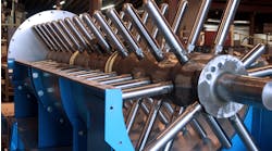
IGCCs are constant-speed machines because complex dynamic situations (rotordynamics, lateral, torsional, etc.) don’t allow variable-speed operation. Many of the machines rely on an inlet guide vane (IGV) to control capacity. IGVs usually consist of a row of aerodynamically shaped blades placed at the inlet of impeller. The blades can rotate around their aerodynamic center to give the suction flow a pre-swirl that provides an optimum incidence angle with the impeller’s leading edge even at reduced flows.
In an IGCC, impellers should achieve high pressure ratios with good efficiency together with a broad operating range. An important aspect is the suppression of surge so the compressor can operate safely and efficiently at reduced flow rates. IGVs that generate a swirling flow in the direction of rotation of the impeller can enhance the underlying stability. In compressors with IGV, the surge usually commences at the peak of the pressure-ratio/mass-flow characteristic. The distance between the surge and the best efficiency point also is relatively small.
Figure 2. The impeller has higher vanes and more of them than an impeller in a conventional centrifugal compressor.
It’s possible to install an IGV for each 3D impeller. Some compressors feature IGV systems at the first two stages or more. However, a common design is to include an IGV only on the first stage.
Using a variable diffuser guide vane might increase a typical IGCC’s operating range. However, such a vane can raise cost, complexity and maintenance, as well as reduce reliability — and so is not a good idea.
The IGV pre-swirl angle significantly influences IGCC performance. Negative IGV pre-swirl angles may be adopted for a flow rate that’s slightly larger than the design (rated) flow rate, and positive pre-swirl angles for lower flow rates or part-loads. There sometimes is confusion about negative and positive IGV angles. A negative IGV pre-swirl angle is an IGV angle in the opposite direction of IGV angles used for part-load (low flow) operation.
The efficiency map usually differs only slightly when a negative pre-swirl angle (for example, in 0° to -20° range) is adopted. The pressure ratio map most often shifts up slightly when the negative pre-swirl angle is increased (for example, from -5° to -10° and then -20°). The performance map of the machine often shows a slightly larger flow rate and a slightly lower efficiency for negative pre-swirl angles compared to zero IGV angle.
The performance map shifts to a smaller flow rate when a positive pre-swirl angle is adopted; the amplitude of its shift could be much larger than it is under negative pre-swirl angles. Large positive IGV pre-swirl angles (say, around +50° to +60°) may cause partial blockage of the flow from the IGV inlet to the impeller inlet, and flow separation on the suction surface of the impeller. In these cases, the corresponding efficiency and pressure ratio can decrease significantly. In general, moderate positive IGV angles (say, in +10° to +40° range) can improve compressor work conditions at low flow rates. Large positive IGV angles may lead to inadequate performance, poor operation, low efficiency and, sometimes, instabilities. IGV pre-swirl angles should be adjusted appropriately under different low flow rates.
For example, a pre-swirl angle of -20° can make the machine work at peak conditions when the highest possible flow/discharge pressure is expected (the highest possible production rate in a chemical processing plant with usually a slightly lower efficiency than the rated efficiency). For this machine, when the IGV pre-swirl angle is moved to +60°, the flow from the IGV inlet to the impeller inlet is almost blocked due to the quite large pre-swirl angle, and flow separation occurs on the suction surface of the impeller.
Changing the IGV angle might suppress the tendency to surge at low flows. For instance, operating at a moderate positive IGV angle (say, +30° or +40°) might provide a suitable reduction on the surge limit. In a case study for the first stage of an IGCC application of +30°, IGV pre-swirl decreased surge flow rates around 15%. This machine required IGV angles greater than +45° to shift the surge point to reduce surge flow rates more than 25%. However, the large angles of IGVs caused a clear drop in efficiency. For this machine (like many others), operation in -20° to +40° IGV angle range likely is optimum, depending on required flow. Using IGV angles more than +40° is possible but inefficient.
Special Considerations
For the last stages of some high-pressure IGCCs, gas may enter the supercritical region. In the supercritical region, the densities of the vapor and liquid phases are essentially the same. (The fluid is known as a “supercritical fluid” rather than a liquid or gas.) Economics often rule out the use of intercoolers for supercritical stages. The compressor performance isn’t usually affected by the supercritical transition because fluid properties (particularly density) don’t drastically change by passing the supercritical threshold.
The control and anti-surge systems of IGCCs need special attention. Ideally, each stage (every impeller) should have an anti-surge valve. However, this isn’t the case for many IGCCs. Some vendors might provide an anti-surge valve for each process stage (uncooled section that may include one or two impellers). Small- or medium-size machines may have only a single anti-surge valve for all the stages. All these cases raise the prospect of complex surge behavior as well as more risks and issues. An IGCC should employ a proper control and anti-surge system to ensure the margin between each stage’s operating points and surge limits remains more or less identical at a certain ratio to avoid differences in stage pressure ratios that, for example, allow one stage to start surging while another operates far from its surge limit.
IGCCs generally are less tolerant to liquid and solid particle ingestion because of their higher impeller tip speeds. So, this issue demands special care. Erosions of impeller blades because of liquid/solid ingestions have been reported.
An Option To Consider
The advantages of IGCCs, such as an optimum speed for each impeller pair, better intercooling, etc., can enable achieving 8–20% better efficiency compared to conventional centrifugal compressors. IGCCs also are cheaper and more compact. However, these machines pose risks and reliability issues that merit consideration during compressor selection and bid evaluations. Dynamic situations, high vibrations, surge issues, high noise, capacity control details, operating range, machine reliability, package availability, reference check for similar services and all other critical factors for IGCCs should be considered for proper design, specification, purchase, installation, operation and maintenance.
The IGV pre-swirl angle significantly influences IGCC performance. In addition, the mechanics of unsteady IGV/impeller/diffuser interactions demand proper assessment. The unsteady effect of the IGV wake and large vortices behind the IGV can affect the aerodynamics of impellers, diffusers and the entire machine. For compressors with IGV, an important frequency of unsteady flow is half the blade passing frequency of the impeller. In some cases, negative IGV angle (an IGV angle in the opposite direction of IGV angles used for part-load operation) could be applied to achieve high flow rates. Positive IGV angles (positive inlet swirl) should be applied for low flow rates.
AMIN ALMASI is a rotating equipment consultant based in Sydney, Australia. E-mail him at [email protected].


