1306-ts-orfice-plate

Think Straight About Orifice Plates

May 21, 2013
Insufficient flow conditioning often undermines measurement accuracy.

Plants frequently rely on differential pressure created by an obstruction in a line to measure flow. Accuracy depends upon two factors: the correctness of the differential pressure measurement obtained via taps upstream and downstream, and the calculation for turning that measurement into a flow rate.
[pullquote]
The obstruction placed in the line most often is an orifice plate — a flat plate with a machined orifice. (For more on orifice plates, see: "Remember the Old Reliable Orifice Plate," for other differential-pressure flow metering options, see: "Look Beyond Orifice Plates.") Orifice plates are cheap and reliable. Moreover, orifice plates manufactured to specific dimensions and tolerances generate known pressure drops for a given flow rate. The International Standards Organization (ISO) has summarized the dimensional criteria; all reputable orifice-plate manufacturers meet these standards.

ISO INSTALLATION REQUIREMENTS

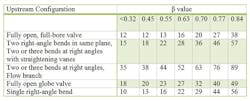
Table 1. Required number of pipe diameters in upstream straight run generally decreases with β value.

ISO standards also cover installation requirements. Proper installation plays a crucial role in achieving accurate orifice-plate measurements. The major criteria include a stable flow pattern, a fluid-filled pipe and an unobstructed flow path (no blockages). If these criteria are met, flow meter calculations can be based on the physical dimensions of the system; no in-place measurement or calibration is required. Let's look in detail at the first requirement, a stable flow pattern. An oft-repeated rule of thumb states that a length of straight-run pipe equal to 10–15 piping diameters creates a sufficiently stable flow pattern. How does this compare to the ISO standards?The ISO standards include multiple upstream piping configurations — from fully open full-bore valves upstream and downstream to multiple right-angle turns to tee-branch connections. They also detail for multiple values of β — the orifice diameter/pipe diameter, in consistent units — the length of straight-run piping required (Table 1). In general, the lower the β, the shorter the pipe run necessary. During piping design, the final β ratio is unknown. So, many engineering standards attempt to reduce overall cost by specifying a maximum β of 0.55 to 0.63.The best cases are fully open full-bore valves with a straight run upstream of them, and a single right-angle bend upstream. The required piping runs for a 0.55 β are 13 diameters for the full-bore valves and 16 diameters for the single right-angle bend. Every other configuration is worse — in some cases, much worse. Higher β values increase upstream requirements.For two 90° bends in series, an orifice with a 0.55 β requires 44 diameters of upstream piping to meet ISO standards. Even with properly installed straightening vanes, this layout needs 22 diameters. A β of 0.84 raises the requirement to 40+ diameters for all types of installations.What this all means is that if your plant needs maximum accuracy, use lots of pipe run upstream of orifice plates. In some cases, 90 diameters are necessary. Additionally, if you're having flow meter problems, check the installation. I've observed many orifice meters inside process units that don't meet ISO standards. The 10–15-diameters rule only applies to a "best case" — i.e., everything else is done correctly and a low-β orifice plate is installed. Most industrial installations require 20+ diameters. Using straightening vanes can help, but doesn't completely solve the problem. The toughest installations are downstream of flow branches and where multiple elbows in series are at right angles to each other. To paraphrase a quote from pump installation guidelines, the only thing worse than one elbow upstream of a flow orifice is two elbows.
BAD IDEA

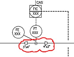
Figure 1. Installing a short section of larger diameter pipe would create flow pattern with unknown impact on meter.

While a plant may start with low-β orifice plates, as hydraulics become tighter it may put in new plates with lower pressure drops (and higher β values). Installing a short run of larger diameter pipe doesn't solve the problem (Figure 1). The upstream expansion creates a flow pattern with unknown effect on the orifice meter.

If the piping configuration doesn't meet ISO standards, accuracy will suffer. For monitoring unit trends, reduced accuracy may be an acceptable tradeoff for a cheaper meter installation. For high and reliable accuracy, always follow the ISO requirements.

ANDREW SLOLEY is a contributing editor to Chemical Processing. You can e-mail him at [email protected].

Sponsored Recommendations

Connect with an Expert!

Our measurement instrumentation experts are available for real-time conversations.

Maximize Green Hydrogen Production with Advanced Instrumentation

Discover the secrets to achieving maximum production output, ensuring safety, and optimizing profitability through advanced PEM electrolysis.

5 Ways to Improve Green Hydrogen Production Using Measurement Technologies

Watch our video to learn how measurement solutions can help solve green hydrogen production challenges today!

How to Solve Green Hydrogen Challenges with Measurement Technologies

Learn How Emerson's Measurement Technologies Tackle Renewable Hydrogen Challenges with Michael Machuca.