|
Related articles IEDCO vacuum conveying system offers compactability and safety
PIAB Vacuum Conveyors offers line of conveyors that can transport 15 tons of powder an hour |
Take the pressure off vacuum systems
Vacuum service imposes certain unique demands on the design of equipment and systems. That is, sizing and design for vacuum differs from that for equipment operating at atmospheric pressure and higher. This article highlights these differences and provides some proven pointers for successful vacuum system design.Some differences apply to any vacuum operation; others come into play only at deep vacuum, that is, at operational pressures below 0.1 Torr (mm. Hg. absolute).
There are four important general differences:
- Pressure drop (“delta P” across the entire system from the user point or user equipment to the vacuum source) is a much greater proportion of the operational pressure. Thus, while a pressure drop of 0.1 in. Hg. is considered acceptable for piping operating above atmospheric pressure, it’s wholly unacceptable if the desired vacuum operation were to be at 0.5 in. Hg.
- A leak in a vacuum system is the reverse of one in a pressure system — air is leaking in not out. Moreover, the air coming into the vacuum system expands because there’s less than atmospheric pressure. For example, 1 SCFM (standard cubic feet per minute) leaking into a vacuum system operating at 0.1 atm. expands to 10 ACFM (actual cubic feet per minute). The deeper the operational vacuum level, the more the in-leaked air expands. This can greatly raise the required capacity of the vacuum source. In contrast, the same leak from a compressed air system wouldn’t increase; compensating for the loss would require only an equivalent small rise in compressor capacity.
- A vacuum system can only go down so much in pressure — after all, perfect vacuum is just -14.7 psi. Because there’s a limit on how much differential a vacuum source can produce (how hard it can pull), there’s a limit on the velocity of the pumped vapors. This limit, which is the sonic velocity, means that the volumetric capacity of pipe can only be boosted for larger flow rates by increasing the diameter of the pipe. This is why vacuum piping is always larger than pipe used at atmospheric pressure or higher. Usually, there’s a several-fold increase in pipe size.
- As the operational vacuum level deepens, heat transfer mechanisms disappear. At atmospheric pressure, three mechanisms transfer heat: convection, conduction and radiation. As operational pressure is lowered, they fall away. By 50 Torr, there’s no convection; by 5 Torr, there’s no conduction, leaving only radiation at deeper vacuum levels. This has a profound effect on sizing, e.g., of condensers and heat exchangers.
Heat transfer only by radiation can provide some practical benefits, such as when a vacuum pump is used with a furnace. The furnace might be operating at 1,000°F but the vacuum pump won’t have problems below 1 Torr if the piping connecting the pump to the furnace is laid out “optically dense” — that is, there’s at least one 90° turn.
Radiation travels in straight lines and must be adsorbed to heat anything. When operating below 1 Torr, the heat can’t get to the vacuum source because the radiation will be adsorbed by the piping. The vapors from the furnace aren’t a heat source as, at 1 Torr and below, they are so dilute the heat quantity carried to the pump is very small (total BTUs are low). Annular pipe arrangements can provide almost “super insulation” if the annular space is evacuated and maintained below 1 Torr.
Pressure drop
The effect of delta P across the piping system is best viewed by looking at the mass flow through a system. A simple material balance across any vacuum system tells us the mass flow out of the equipment must be matched by the mass-handling capacity of the vacuum source.
Per the ideal gas law, the mass equals the product of the operational pressure and the pumped gas volume. So, for a piece of vacuum equipment operating at 10 Torr with 100 ACFM of vapor being removed by the vacuum system, mass flow is 1,000 Torr-CFM (10 Torr × 100 ACFM). The vacuum source would have to have an equivalent mass-handling capacity, 1,000 Torr-CFM. However, it would have to handle that mass of gas at the vacuum level of the user equipment plus the pressure drop across the piping connecting the equipment to the vacuum source. In our example, if there were a 1 Torr pressure difference due to the design and sizing of the pipe, the vacuum source would have to handle the flow at 9 Torr (the operational pressure of the equipment minus the pressure drop) because the pressure would have to be lower at the vacuum source for flow to be in the direction of the vacuum source.
The same mass flow, 1,000 Torr-CFM, handled at 9 Torr produces a vacuum capacity requirement of 111 ACFM, not 100 ACFM (1,000/9 = 111). So, the 10% pressure drop increases the size of the vacuum source by 11%.
The generally accepted criterion of a well-designed vacuum system is that the pressure drop across the entire system not exceed 10% of the operational pressure.
Air in-leak
The expansion of in-leaks makes the requirement of the tightness of a vacuum system much more critical than in a compressed air system. There’s debate in the vacuum industry over the acceptable amount of in-leak. Of course the deeper the level of vacuum used the less in-leak that can be tolerated.
Remember that, besides its impact on the vacuum system, an in-leak also may ruin the product. For example, in the semiconductor industry, oxygen from an air in-leak can chemically react with silane to produce sand, SiO2, not the desired semiconducting solid.
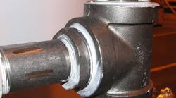
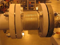
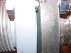
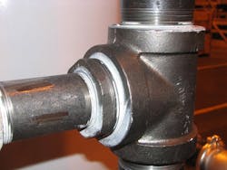
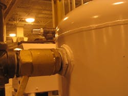
Piping practices suitable for pressure operations often aren’t sufficiently tight for vacuum operation. One common example is the use of threaded connections (Figure 1). While they work well for applications at atmospheric pressure and above, they aren’t good for vacuum because it pulls apart the mating thread surfaces responsible for sealing. The sidebar provides some more tips about piping design, while Figures 2–4 illustrate some proper practices.
Figure 1. Threaded connections shouldn’t be used in vacuum systems unless properly sealed.
Figure 2. For pumps in high vacuum systems, always install a seal disk, as shown above.
Figure 3. Employ a metal bellows connector to take pipe stress out of a system with a piece of rotating equipment.
Figure 4. Gap is a tip-off to use of raised face or pressure flanges, which will require “high durable” gasket for vacuum service.
High vacuum design
As the operational pressure deepens all these effects continue to magnify. At really low levels of vacuum (below 0.1 Torr), what may seem like minor things begin to be very important in design:
- Cleanliness. This is essential to reach and maintain a high vacuum. Any dirt, liquid or oil will slowly offgas unless it has a very low vapor pressure, degrading the vacuum. So, ordinary oils and lubricants won’t do. Before use in the high vacuum chamber they all must be “pre-outgassed” or held in a deep vacuum until all volatilization has ceased. Even small smudges or fingerprints on the vacuum side of a vessel will outgas.
- Metal surface smoothness. Small nooks and crannies on the metal surface can adsorb air and other gases, which then offgas slowly, degrading vacuum level. To prevent adsorption, deep vacuum vessels usually must have the surfaces facing vacuum polished.
- Elastomers. Flexible materials used in gaskets, o-rings and seals can outgas at deep vacuum. Elastomers also can lose their dimensional memory as they expand and contract with the cycling of the vacuum system, and thus not completely seal all surfaces. In fact, metal gaskets or special o-rings called sealing discs (o-rings with metal “winglets”) often are needed to prevent leaks in joints, flanges, etc.
The techniques used in so-called high vacuum design become necessary when the operational pressure level falls below 1 Torr. They really constitute the best available technology and should be considered to improve the quality of any vacuum system.
Unfortunately, they all too often are dismissed as too expensive. The difference in cost between a flanged connection and a threaded connection may be the most extreme example. However, low-pressure-drop layout of the piping, inside wall smoothness, hard elastomers, etc. can make any system, regardless of its operational vacuum level, operate more efficiently. That is, they help deliver more of the vacuum source’s capacity to the user equipment and thus contribute to the overall economics of the vacuum system.
Proper testing
It’s essential to periodically check your vacuum system for the development of in-leak.
The most common method is the “rate-of-rise” test. In it, the system is pumped down below its usual operating pressure and valved off (isolated from the vacuum source).
So, the only way the pressure can rise is due to the in-leak of air. The deeper the operational vacuum used the less air in-leak that can be tolerated. Industrial systems shouldn’t increase more than 10% from the base pressure in 24 hours. High vacuum systems need a more strenuous standard, especially if the processes can’t tolerate the presence of oxygen (as in most semiconductor systems). Here, the generally accepted standard as a 1% rise from the base pressure in 24 hours.
There’s a temptation in industrial or “rough” vacuum operations to use pressurization methods to test the system (either with water, as in a pressure or hydrostatic test, or with compressed air). However, they only will give a very rough indication of the tightness of a system. Water is a liquid and its surface tension reduces in-leak. In addition, many components such as seals in a vacuum system are directional in nature and pressure testing is looking for flow in the wrong direction (vacuum leaks are in-leaks).
Henry H. Hesser is a staff technical specialist for Busch, LLC, Virginia Beach, Va. Reach him via e-mail at [email protected].
Piping pointers
Vacuum systems will provide better performance if you follow these eight tips:
- Minimize bends in the piping layout. Every bend, every change in direction, etc., adds to pressure drop.
- Wherever elbows are required, use long-radius instead of short-radius ones to reduce pressure drop.
- Wherever two lines come together, use a wye instead of a tee to lower pressure drop.
- Make sure that the overall pressure drop of the piping (farthest use point to the source of vacuum) doesn’t exceed 10% of the operating pressure.
- Eliminate unsealed threads wherever they are used. They are a large source of leaks. Always remember that whatever leaks into the vacuum system expands greatly. Two ways to lessen the impact of threads are to use a sealer in the gaps of normal NPR threads or use NPT “fine cut” threads.
- Tighten flanges, regardless of type, by working in turn on “opposites” or “facing” bolts, not clockwise or counterclockwise in succession.
- Check every elastomer (gasket, o-ring, etc.). Each should be “hard” (greater than 90 durameter) to eliminate leaks arising from pressure cycling (up, down, up, etc.).
- Keep the rate-of-rise over 24 hours of the piping system to 10% or less of the operating pressure and test regularly.
