Gas-fueled internal-combustion engines fueled by gas play an important role at many chemical plants as drivers for equipment such as compressors, pumps, generators and blowers. These engines often handle a variety of services at a site — for instance, to transport liquid or gas fuels within the facility and to meet process compression needs (such as refrigeration cycles). They are versatile prime movers capable of reliable and efficient operation. The medium-speed reciprocating engines that are used offer inherently high thermal efficiencies as well as attractive costs and operational characteristics. They operate at 300–1,000 rpm and come in sizes from 30 kW to 20 MW.
The engines can use a wide variety of fuel types and grades, including sour, sweet and wet gas. Economic factors associated with energy conservation, depletion of existing resources and increasing transportation costs will promote the use of alternative gas fuels, particularly at remote locations with abundant available cheap gases and at small sites with limited electric power.
The engines have benefited from extensive improvements and refinements since they were introduced around 80 years ago. For instance, the specific power output of the major engine types has doubled every ten years or so. Further developments likely will enable gas engines to offer power ratings and consumption levels that match those of the most modern diesel engines and, long term, that rival those of other well-known drivers.
Combustion Issues
Initiating the combustion in a controlled manner in a reciprocating internal-combustion engine is significantly more difficult with gases than with liquid fuels.
Detonation — uncontrolled combustion with ignition occurring spontaneously throughout the mixture — can cause a considerable rate of pressure rise that invariably harms the mechanical structure of engine components. Therefore, gaseous fuels are classified according to their inherent tendency to detonate in the engine. The characteristic of the fuel may set the engine ratings. Overall, combustion control in the engine focuses on preventing detonation.

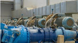
Figure 1. This engine is located in a utility area of a plant.
In a gas-burning engine, the prime objective is to achieve controlled combustion at a predetermined point. This requires compressing the gas and air mixture while maintaining the mixture within the flammability limits — without promoting spontaneous or self-ignition in the increasing temperature and pressure environment of the cylinder.
Conventionally, either an electric spark or injection of a small quantity of fuel with a high “cetane index” initiates combustion by the propagation of a flame front throughout the mixture. To achieve this controlled process, it clearly is essential to use gaseous fuels that won’t auto-ignite or detonate in the prevailing cylinder conditions. Such fuels include natural gases and even some low calorific gases. Work continues to broaden the spectrum of gases that can be successfully utilized, increase the ratings and achieve fuel consumptions comparable to those of diesel engines.
In the past, developments focused on preventing detonation by reducing engine rating, lowering the engine compression ratio to decrease the end-of-compression temperature, and increasing the air excess — characteristics that cut the potential volumetric power of engines and boost fuel consumption. Another issue involved the need to promote controlled ignition by external means. These issues now have been successfully addressed. So, development efforts have turned to improving the ability of engines to operate at high efficiency with minimum service, maintenance and overhaul costs and with increasingly poor quality fuels.
Expanding Application
In recent years, reciprocating engines have gained increasing favor as medium- and large-scale mechanical drivers for compressors, pumps, generators and other equipment. Advances in technology have enabled commercialization of larger capacity, better efficiency, dual-fuel capable, and higher availability engines. Large reciprocating engines used in plants and facilities generally are in the 1–20-MW capacity range. They typically operate at medium speed (400–1,000 rpm, depending on capacity and grid frequency) due to tradeoffs between performance and operational life and maintenance interval requirements for continuous operation. Lower-speed engines (<400 rpm) feature low dynamic performance and massive physical size and weight, due to low power intensity (output per unit of volume/displacement) related to the low speed, and, so, are less attractive than medium-speed engines. These advantages have made large reciprocating engines especially attractive for different mechanical drives.
The reciprocating engines, of course, should meet plant requirements and specifications, including emissions, availability, speed control, heat-rate, step-load response requirements, part-load operation, etc. The engine’s step-load response often is neglected in the manufacturer’s performance guarantee but could prove to be a major issue for some applications. Unlike the well-established response to load changes in gas and steam turbines, medium- to large-scale reciprocating gas engines’ speed control performance and response to load changes are relatively new areas.
Step loads are fast load changes in the driven equipment’s mechanical power requirement. For a typical application, three types of load imbalance can occur instantaneously:
• insufficient supply of pumped fluid, compressed gas or generated electrical power because of failure of a machinery train (such as a compressor or a generator);
• substantial change in engine power due to failure of a component in an upstream or downstream machinery train that results either in power oversupply or undersupply, depending on the location of the equipment.
• sudden rise or fall in demand stemming from a major change in the plant, particularly downstream.

Figure 2. Dismantling of unit showed accumulated internal dirt that contributed to failure of this engine.
Gas engines respond to the load imbalance by increasing or decreasing shaft power output. The response won’t be instantaneous mainly due to time lag in the engine’s mechanical components that control the fuel and air input. During this lag, the engine’s speed will go up or down in response to the load imbalance; the maximum speed change is a function of its starting point and system inertia, for example, mass and speed of the engine rotor. Reciprocating engines might have lower inertia compared to gas or steam turbines, unless proper flywheel(s) are used in the trains. The speed change of reciprocating engines depends on engine design, load imbalance, engine load factor (ratio between initial load and engine net capacity) and fuel type (fuel gas details). The maximum allowable step load can be determined by the engine’s load factor and train details. Dual-fuel (diesel or gas) engines usually have a higher step load capability in diesel mode.
Reciprocating engines typically allow equal or larger step load decrease than step load increase for the same speed change. Usually, you should focus more on step load increase because it causes more stress to the engine rotor and requires a narrower operation range than step load decrease. To meet the step-load-increase requirement, an operating engine should maintain some level of spinning reserve above actual power demand by the driven equipment. Variable-load capability and speed change represent key issues for a reciprocating engine used in medium- to large-scale applications.
Oil And Sealing
The primary difference between engine oils for gas engines and those for other internal combustion engines is the necessity to withstand some degradation issues unique to the gas fuel combustion process. These include the accumulation of oxides of nitrogen, a condition commonly called “nitration,” which should be monitored regularly to safeguard both oil and engine life. Sulfated ash content is another consideration unique to gas engine oils, particularly for natural-gas engines.
Engine oils vary with engine design and operating conditions; they range from simple uninhibited mineral oils, to medium-to-high-ash, alkaline and oxidation-inhibited detergent oils, to totally ash-less, yet highly detergent types. Selecting the most cost-effective oil that enables achieving maximum efficiency and long life from the engine demands careful consideration of engine design and operating conditions. Pay special attention to oxidation stability, high-temperature thermal stability and frictional characteristics. In most plants where gas engines operate, exhaust emissions have become a serious concern. To control or eliminate these emissions, some current engine designs require catalytic converters, which limit the additive types and the formulated percentage levels that can be used in the engine oil. In many cases, a well-designed oil can provide sustainability benefits besides extending engine and oil life — i.e., less oil for disposition and higher energy efficiency.
Proper oil-condition-monitoring techniques are essential. Provide suitable monitoring systems to evaluate the oil life, piston cleanliness and wear performance of oil.
It is important to note that, unlike diesel or gasoline engines, gas engines can burn large quantities of oil during operation. Some reports put the typical oil consumption rate for some gas engines at around 1 g/kWh — or roughly 0.6 kg or 1 liter per month. However, many gas engines should consume oil at less than 5% of this rate.
Piston rings play an important role in the performance and endurance of a gas engine. They have to provide optimum sealing while minimizing wear and friction at the same time. The lubrication oil consumption and blow-by in an engine directly relates to the sealing function of the piston rings. The need to meet stricter emission norms mandates reduction in lubrication oil consumption because of its very high impact on the emission of particulate matter. Achieving low oil consumption sometimes involves trial and error. The better way to understand the piston ring dynamics and complex phenomenon of gas dynamics is to use a simulation tool and proper testing having a fair degree of accuracy. There should be no oil starvation during the complete operating cycle of the engine — to avoid the risk of metal-to-metal contact. Oil throw-off from the top ring usually is a major factor in consumption. The oil consumption generally rises with increasing engine speed, as does blow-by. In a case study, the oil consumption climbed by 18% as engine speed went from 1,800 to 2,400 rpm. In another case study, the oil consumption rose by 10% as engine speed went from 2,600 to 3,200 rpm.
AMIN ALMASI is a rotating equipment consultant based in Sydney, Australia. E-mail him at [email protected].