Ease Burner Management System Upgrades
Many plants must contend with outdated burner management systems (BMSs) on all sorts of equipment — boilers, process heaters, thermal oxidizers, incinerators, reformers, vaporizers, dryers, ovens, sulfur recovery units, kilns, calciners, furnaces, etc. Some of these brownfield installations may date back 40 years or more. Most systems originally were designed according to prescriptive standards, almost a “cookbook” approach. Numerous logic systems in use still are based on relays or other technologies that are becoming obsolete and difficult to support. Many older fuel-train-valve arrangements are non-redundant, yet current standards mandate double-block-and-vent valves. Myriad existing systems require a variety of changes and upgrades — but trying to bring all systems up to current standards is both problematic and potentially very costly.
For example, some systems have 40 or more fuel lines. Installing extra block-and-vent lines (per current codes) would be cost prohibitive, especially considering that many companies have numerous such systems at multiple sites.
However, some interesting things have happened with standards in the last ten years. Back when the ISA 84 committee started working on the technical report for BMSs, most of the prescriptive BMS standards in industry — such as those from the National Fire Protection Association (NFPA) and American Petroleum Institute (API) — had not embraced or invoked the safety lifecycle. As of 2015, all the BMS series of NFPA standards (85, 86 and 87) have invoked the safety lifecycle. For brownfield installations with perhaps dozens of very similar systems that may require upgrades, this represents a significant opportunity.
[javascriptSnippet ]
Seizing The Opportunity
You must take two steps to achieve savings for brownfield BMS upgrade projects where you wish to apply the lifecycle approach.
Step one is to develop an “equivalent design” to what is in the NFPA standards. This doesn’t mean that what NFPA cites is “wrong” but rather that you are allowed to come up with an equivalent design and show it’s acceptable. A design that doesn’t require a separate master-fuel trip relay or dual block-and-vent valves for every fuel line represents significant potential cost savings. As long as the authority having jurisdiction (AHJ) approves the design, such an approach is acceptable. This first step is not the focus of this article.
Step two is to use “templatization” to further reduce the costs of implementing the safety lifecycle on multiple similar installations. We have found doing so typically provides overall savings of roughly 60%. This article focuses on step two.
Templatization
If you are going to use an equivalent design, the NFPA standards state you must follow the safety lifecycle in its entirety. Therefore, you must do process-hazards and layer-of-protection analyses, perform hardware verification calculations, develop a safety requirements specification (see “Bridge the Gap”), formulate test plans, and more.
Imagine your firm uses a single-burner, single-fuel NFPA-85 boiler at multiple sites (which is quite common for most operating companies). All the boilers will be very similar. Once you had engineered the first boiler, if you then could copy and paste for all the others, you’d gain a significant reduction in costs and schedule. You could further expand this to the instrumentation and controls design.
Such an approach allows re-use of a variety of project deliverables, including:
• approved vendor lists for instrumentation in line with safety integrity level (SIL) calculation assumptions;
• instrument datasheets;
• instrument index;
• input/output (I/O) list;
• control panel design with bill of materials;
• control system architecture diagram;
• instrumentation and electrical installation details;
• control panel internal wiring diagrams;
• field wiring diagrams (loops/swing arms/schematics);
• cable/conduit block diagrams;
• cable schedule;
• software requirements specification;
• logic solver configuration;
• logic solver simulation logic;
• local human/machine interface (HMI) design and configuration;
• remote (control system) HMI design and configuration;
• historian configuration;
• factory acceptance test procedure and factory acceptance testing (FAT);
• site acceptance test procedure and testing; and
• commissioning test procedure and testing.
Broader Utility
The operations and maintenance phase of the NFPA-85 boilers, which is a significant portion of the lifecycle and where you identify bad actors and remove risk from the business, also offers plenty of opportunities for engineering once and then cutting and pasting. Functional test plans are required for all field devices. Calibration and test plans must be loaded into a computerized maintenance management system. Test intervals must match the assumptions made in the hardware SIL-verification calculations. You need spare parts in line with repair-time assumptions. Operations and maintenance staff must get trained on the new systems. Personnel or software need to track the amount of time safety functions are in bypass, demand frequencies, initiating event frequencies, failure rates, late or incomplete testing, and more.
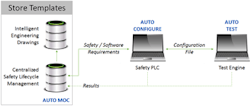
Figure 1. Synchronizing a safety-lifecycle database with an intelligent drawing package enables generation of templates.
This documentation must be in place to follow the NFPA 85/86/87 and ISA 84 standards. The goal is to do this as cost effectively as possible because such efforts won’t produce more product or improve product quality. You need to reduce the man-hours as much as possible while still driving consistency and quality. So, how could this be done?
The suggested approach (Figure 1) requires a centralized safety-lifecycle-management database to handle all the engineering deliverables, as well as an intelligent drawing package. Synchronizing the two enables developing templates for deliverables such as SIL-verification calculations and loop sheets. After you’ve already engineered a couple of these things, what are you really changing? Tag numbers. You then can take safety and software requirements and port them over to the safety programmable logic controller (PLC) logic solver. Depending upon the vintage and sophistication of that unit, you can auto-configure a number of things. Some technologies available today have significant auto-configuration capabilities. As a minimum, you can configure calibrated ranges, I/O point assignments and descriptions, and even some logic definition. With the mantra of “work smarter, not harder,” you can do some kind of personal-computer-based emulation to auto-test the logic much more thoroughly than you might do by brute force. As a precursor to FAT, you would have to pass this auto-test.
There’s also the potential for automatic management of change (MOC). For example, imagine it’s 3:00 am and things aren’t going well. Someone alters the purge timer to five hours from five minutes. Every time you make a change in the PLC, the file could be dumped to the same location and you could run the new configuration output in the test engine against the last-known previously good test. In this case, the test would fail and you then could find the cause. You could perform such a check once a week or once a month. This would ensure that if you are doing MOC: a) you start with the safety instrumented system (SIS) design requirements; b) it goes into the safety PLC configurator; c) it is adequately tested; and d) you have a validated test against the original requirements.
Taking this approach can reduce the cost of engineering as well as improve quality and consistency. It even can shorten the time for FAT by auto-testing the templates. This is especially useful in the BMS world where the same things are done over and over again. A side benefit is the loop back for the automatic MOC. The approach potentially might alter the culture in your organization — ensuring changes that might impact functional safety aren’t made at the 11th hour but go through a rigorous MOC process.
Work Smarter Not Harder
Industry now can take advantage of the benefits of automation to drive consistency, reduce costs and schedules, and, more importantly, deliver a safety-instrumented BMS that looks at all the pieces, including the engineering automation, the SIS, and the FAT. This also will help with day-to-day operations and upkeep.
To do this, you’ll need templates for a single-burner boiler, an incinerator, a reboiler, etc. You’ll have to go through your organization to figure out what combination of fired devices it has, come up with a design basis, and start developing the templates. A qualified functional safety professional should review and approve the templates. You must test all the templates thoroughly, place them in a library of templates that are maintained under MOC, and ensure they only originate from that trusted library. You could have a small, dedicated team execute this, reduce the interfaces between resources on your project (engineering, construction, etc.) and keep your costs in line. This will set you up for success.
In addition, you should establish a continuous improvement mechanism so you can refine the templates based on learnings from their use.
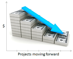
Doing all this can dramatically lower costs. The first project might cost $X but, by using the template approach on every project after that, you should be able to quickly drive the costs down to a very low level.
“Copy” is a four-letter word for a reason. We don’t expect each NFPA-85 boiler to be identical. A boiler installed in 1977 likely will differ from one commissioned in 1985 from an operations and maintenance perspective. However, the two boilers probably will match in about 70% of things. So, for that 70%, you can take advantage of “copy and paste.” You end up fully engineering at normal engineering rates only the 30% of oddball different items. This also will help shorten the schedule.
Our actual experience doing this on repeat BMS projects indicates the level of overall savings can be as high as 75% on the safety lifecycle, 70% on the control system design and integration, and 35% on the operation and maintenance activities. As already noted, the combined overall savings are roughly 60%. It comes down to how many unique templates you have and whether it’s possible to treat this as a “program” rather than individual islands of projects that don’t take advantage of the templates and the copy factor. Considering the current price of oil, this level of savings is phenomenal.
Figure 2. After developing templates for the first upgrade, the cost of subsequent projects dramatically decreases.
Improve Your Approach
First, don’t automatically accept the prescriptive cookbook requirements in the NFPA standards. Instead, come up with an equivalent design for the safety instrumented BMS following the safety lifecycle and get it approved by the AHJ. Build the most-cost-effective solution that meets the risk-reduction requirements for your facility. Second, to maximize your savings, take advantage of the programmatic templatization approach for multiple units with common functionality.
Major Company Benefits From Templatization
A large global oil, gas and chemicals company, after conducting a field survey of more than 80 fired devices, determined it needed an upgrade project to meet new corporate safety standards, ensure code compliance and replace obsolete BMS-related controls. So, in early 2014, the company launched an eight-year program — to design templates, complete detailed design, commissioning and construction — that would take advantage of already scheduled planned outages. The initiative involves collaboration by the company’s capital projects group, its operations and maintenance staff, and a system integrator familiar with BMSs.
To achieve savings both in cost and schedule, the company mandated use of templatization. Early results are very positive. The first several BMS upgrades likely will yield a savings of $70,000. As the program progresses, continuous improvement sessions are planned to brainstorm additional ways to reduce costs and shorten the schedule even further. Overall, the company should save at least $6.5 million over the entire course of the program.
MIKE SCOTT, P.E., CFSE, is Anchorage, Alaska-based executive vice president, global process safety technology, for aeSolutions. PAUL GRUHN, P.E., CFSE, is global functional safety consultant for aeSolutions in Houston. E-mail them at [email protected] and [email protected].


