The boiler feedwater (BFW) pumping system is a vital part of steam generation units that play an essential role at many chemical plants. So, dependable operation of BFW pumps is crucial.
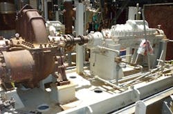
COMMON CHOICE
Figure 1. This axially split multistage between-bearing pump, in this case driven by a steam turbine, is designated as “BB3” in API-610.
ALTERNATIVE PUMP
Figure 2. Some sites install non-API pumps such as this one.
DESIGN AND FABRICATIONToday’s BFW pump designs are less sensitive to mechanical fault and can survive malfunctions and disturbed suction conditions without failure. Nevertheless, a BFW pump system should contain two pumps, one operating and one standby. Because of the criticality of the BFW service, pumps needing attention should be repaired as quickly as possible, to minimize time without a spare in place.The design of the BFW pump should facilitate fast repair in the event of breakdown or damage by enabling easy removal of all working parts from the outer casing and their replacement with an assembled element. The target changeover time usually is less than 10 hours. The internal stages, together with seal and bearing assemblies, usually come as a complete assembly, known as a “cartridge,” that can be removed and inserted into the pump casing from the non-drive end. This allows all work to be carried out without disturbing the driver or the piping. The high speeds can result in impellers of relatively small diameter. These lead to small casing inner diameters and, hence, thinner casings to withstand the hoop stresses. In turn, this translates into lower thermal stresses during transients, making the pumps more reliable.Many textbooks and papers in the literature disregard the casing or diffuser, and assume best efficiency only depends upon impeller design, particularly on the flow at the impeller vane angle. However, the casing and the diffuser shouldn’t be neglected; their design requires proper care. For instance, the impeller-outlet flow area and casing-throat area can influence pump performance and reliability. Their correct design underpins many successful centrifugal pumps. For a small impeller-outlet flow area and a large casing-throat area, the high backward velocity reduces the whirl and thereby lowers the head. At the other extreme, a large impeller-outlet area and a small casing-throat area will give a high throat velocity. If these areas aren’t designed properly, recirculation could occur and lead to destructive vibration. In cases of high power concentration, these vibrations could reduce the life of the pump to a few weeks. This points up the importance of proper adjustments of impeller-outlet flow area and casing-throat area.Stainless steels commonly are used in BFW pumps. Components in horizontally split medium-pressure BFW pumps often are fabricated from suitable grades of corrosion/erosion-resistant stainless steel, such as chrome or chrome-nickel alloy types like “12% CHR” or similar. Because some stainless steels offer relatively low ultimate tensile or yield strength, the pressure casing of vertically split high-pressure BFW pumps usually is manufactured from low alloy or suitable carbon steels. Too often, the design of pump casings focuses mainly on deflections (strains). Special care is required because BFW pumps often are fabricated from a variety of materials with different rates of thermal expansion.The joint design is critical in high-pressure BFW pumps. As the pump pressure increases, the joint bolting becomes more heavily loaded, which tends to reduce the interface pressure at the joint faces. The number of bolts that can be fitted around the joint is finite. Closed-type impellers commonly are used in BFW pumps. They are less sensitive to axial position and, therefore, preferable for relatively long shaft assemblies where axial displacement due to thermal movements or thrust may be substantial. The selection and sizing of BFW pumps also need careful attention. These pumps often are specified for a rated capacity about 20% in excess of the normal working load. Limiting the number of types and sizes of BFW pumps used at a site provides important benefits. Such standardization contributes to effective operation and easy maintenance, and minimizes inventory of spare parts. Pump manufacturers usually offer their BFW pumps in pre-designed models. For example, one vendor covers the commonly used range of 160–720 m3/h by 9 frames. Each frame is around 15–30% larger than the previous one. The frame series comes in capacities of 160, 210, 260, 320, 380, 430, 500, 580, and 720 m3/h. Opt for BFW pumps from a well-known pump manufacturer with sufficient number of frames available for the range required. Ensure the selected rated point is very close to the best efficiency point (BEP) of the pump (preferably from -11% to +4%). It’s critical that the pump manufacturer have a proper frame (model) for the targeted application, i.e., a reasonable match. For example, for a large chemical processing complex with main boiler pressure of 110 Barg with steam generation capacity of around 35 MW, the BFW pumps each could provide 160 m3/h for 145 Barg rated pressure. In this case, the pumps were 10-stage traditional pumps operated at around 3,000 rpm. The distance between the rated point and the BEP was just -2.5%, i.e., rated flow was 97.5% of the BEP flow. SUCTION CONCERNSBFW pumps are vulnerable to disturbances to the suction. Loss of water or reduction in net positive suction head (NPSH), even momentarily, likely will result in operational problems such as metallic contact, leading to seizure.Specifications most often require that a BFW pump be capable of surviving loss of water. The pump usually should be capable of enduring very badly disturbed suction conditions with the NPSH reduced substantially below that normally required, as may occur during a sudden, substantial load rejection. Practically the only way a BFW pump could run dry in service is if the suction isolating valve were to be shut accidentally. However, a pump that can survive being run substantially dry usually should be able to withstand the worst disturbances that may be expected in suction conditions. Sometimes, an end-user specifies dry running capabilities. A high-speed, high-pressure BFW pump sometimes relies on a low-speed booster pump to prevent cavitation. The booster pump delivers BFW into the main pump, thus, protecting it from cavitation. The booster pump may have a separate drive or can be driven by the main pump driver through a speed reduction gear in the same pump train. The usual available height (from a deaerator tank above the BFW pump) is about 6–14 m. For commonly used BFW pumps, this available height requires careful suction-piping sizing and design to avoid cavitation. DRIVERSThe power needed to drive a BFW pump is an almost linear function of the steam pressure. For modern high-efficiency steam-turbine mechanical drive or power generation systems, this means that even though the steam mass flow and, consequently, the BFW mass flow are reduced and the efficiency of the pump is improved, the pump power rating increases.A variety of drive configurations can be used, including:• a motor with a variable-speed drive (VSD);• a condensing steam turbine; or• a backpressure steam turbine.Induction-type squirrel-cage electric motors are popular for BFW pump drives. The efficiency of advanced electric motors can exceed 97%. The characteristic curves of the efficiency of modern motors often are relatively flat, which is of utmost importance for operation at partial load. Typically, the efficiency of a steam turbine driver ranges from 88% to 93%, depending upon steam turbine details. A condensing-steam-turbine driver for a BFW pump often is fed with the intermediate-pressure steam from the outlet of a large steam turbine or steam from the intermediate-pressure turbine bleeds; the unit sends steam to a combined (large) condenser or an additional independent condenser. In the case of large, high-pressure steam-generation units, the relatively high speeds needed for the BFW pump (5,500 rpm or greater) may rule out a condensing steam turbine. Due to the high speed required by many BFW pumps, the peripheral velocities of the last stages differ considerably from the optimum values that ensure the highest efficiency. Combining high peripheral velocities with long blades often causes mechanical problems.The efficiency of relatively small condensing steam turbines employed to drive BFW pumps often is 5–10% lower than that of modern, large steam turbines used in mechanical drive or power generation trains. Some steam turbine manufacturers offer reaction-type condensing steam turbines with a fully separated flow with the steam inlet in the middle and symmetrical outlets. This leads to rotor elongation, which might not be a serious problem for reaction-type machines because the mechanical problems related to long blades often are solvable. The efficiency level of these steam turbines is just 3–4% lower than modern, large steam turbines. However, such machines are very expensive. Generally, condensing steam turbines aren’t popular for BFW pumps except for extremely large units and special plants. Condensing steam turbines have been used in the 9–16-MW power rating range for BFW pumps. For example, a 9-MW, 4,700-rpm condensing steam turbine drives the pump of an extremely large steam generation system that supplies high-pressure steam for a ∼380-MW complex for the combined mechanical drive (compressor and pump drivers) and power generation operation. This pump accounts for ∼2.3% of the total power. A backpressure steam turbine doesn’t require a costly system of the condenser and cooling water, which usually is necessary with the condensing turbine driving a BFW pump. A common arrangement for a modern BFW pump system is a main (operating) pump with a robust backpressure steam-turbine driver and a standby pump with an electric motor and VSD.
AMIN ALMASI is a rotating equipment consultant based in Brisbane, Australia. E-mail him at [email protected].
