Consider VFDs for Centrifugal Pumps
Variable frequency drives (VFD) offer a useful control option for the motors of many types of reciprocating and centrifugal equipment. For instance, VFDs can deal with centrifugal-pump suction recirculation problems; running at lower speed can help reduce damage and operating difficulties.
[pullquote]
To understand how to apply VFDs effectively, you must know the characteristics of the system and the equipment. So, let’s look at a general procedure that can serve as a good starting point for evaluating specific cases — realizing, of course, that it can’t cover every possibility.
To evaluate a VFD application, we need the following:
• system information on pressure drop versus flow;
• pump performance curves for the existing impeller;
• pump performance curves for the maximum impeller; and
• pump inlet eye dimensions.
Ideally, the performance curves should include pump head, pump efficiency and net positive suction head (NPSH) required versus flow rate. Pump heads and efficiencies at various speeds are useful.
Often, only incomplete information is available. So, you may need to extrapolate to fill in missing information.
ANALYSIS PROCEDURE
A VFD evaluation involves multiple steps, each looking at a specific item. Below are the basic steps. (Some cases won’t need every step while others may require additional ones. The information available and needed as well as the number of cases to be evaluated determine what must be done.)
1. Define the system curve.
2. Examine the pump curve for the existing impeller at fixed speed.
3. Plot a flow rate versus speed curve for the installed impeller.
4. Determine the best efficiency point (BEP) flow rate versus speed for the maximum impeller.
5. Examine NPSH versus flow rate.
6. Plot flow rate versus suction specific speed (Nss) for using the VFD to control.
7. Define operating fraction of BEP flow versus Nss.
8. Compare the operating flow fraction versus Nss to good practice.
9. Evaluate pump suction energy to determine the NPSH margin.
10. Check power available.
11. If the results of operating flow fraction versus Nssand pump suction energy evaluation are unacceptable, assess alternative solutions.
The system curve plots the required differential head versus flow rate. The system curve includes both static head requirements for elevation and pressure change and dynamic head requirements from pressure drop.
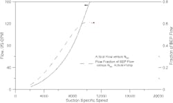
Figure 1. Combined plot shows both flow and fraction of BEP flow versus Nss.
ANDREW SLOLEY, is a Chemical Processing contributing editor. You can e-mail him at [email protected]
REFERENCES
1. Sloley, A. W., “Cut Pump Speed to Cut Problems,” Chemical Processing, September 2009.
2. ANSI/HI 9.6.3-2012, “Rotodynamic (Centrifugal and Vertical) Pumps — Guideline for Allowable Operating Region,” Hydraulic Institute, Parsippany, N.J. (2012).
3. Burdis, A. R., “Improved Pump Hydraulic Selection Reduces Cavitation Risk,” p. 39, Hydrocarbon Processing, August 2004.
4. Sloley, A. W., “Properly Protect Centrifugal Pumps,” Chemical Processing, July 2007.