Keep Current on Your Electrical Measurement Equipment
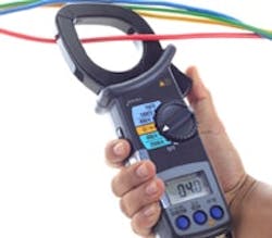
It's tempting to use highly sophisticated tools for troubleshooting. After all, you want to show you're taking advantage of the expensive gear. However, a fairly rudimentary device often may suffice. The clamp meter is a good example — it's a simple but useful tool for diagnosing equipment powered by alternating current (AC).
The meter measures the current induced in a coil in a clamp placed around a wire or motor lead. You need an accurate value of current to estimate the power supplied to motors for rotating equipment and then, perhaps with some guesswork, to gauge motor efficiency. You can improve accuracy by measuring the actual voltage delivered to the motor starter and, if possible, the phase lag of the AC current. As a rough guide for lag, use the ratio of the estimated current based on loading and the supplied current. If baseline data are taken, studies can detect bearing wear, poor seal performance, changes to the process conditions or fluid, or even a broken or worn impeller.
Before taking measurements on new motors and starters or ones recently repaired, it's critical to check that their frequency and voltage ratings are correct. This means matching component serial numbers. I've received the wrong starter heater from a manufacturer. The wrong heater was packed in the wrong box and shipped throughout the world! My electrician should have gotten a finder's fee for uncovering that mistake.
A common problem is receiving a 60-Hz motor for a 50-Hz application or vice versa. In the first case, you lose some of your motor cooling and horsepower because the motor is turning at 80% of its rated speed — for example, a 10-hp motor becomes an 8-hp motor. In the second case, the cooling increases 20% along with the horsepower and current draw; provided the current reading is less than the motor's full load amp rating and the rest of the electrical system can handle the load, you might get away with it. Usually, though, using the wrong frequency eventually will harm the motor.
With single-phase AC, it's always a bad idea to mismatch the frequency between the motor nameplate and the supply. Single-phase motors can't use the attraction between different phases to initiate rotation. They induce shaft rotation by the play between two separate coils — so-called split-phase induction. With a mismatch, the rotation might not occur or the shaft might not spin with sufficient speed — overheating and fire can result.
Assuming a motor passes checkout, you can use current measurement to investigate problems with related electrical equipment. Readings can show an unbalanced load in the leads (L1, L2 and neutral) from a motor bucket or problems in the motor starter itself. A current deviation exceeding 10% between leads or from lead to ground can cause overheating; similarly, a variation in the voltage between on and off conditions indicates a problem.
More complex problems such as failures in variable-speed drives and motor starters or difficulties during startup and shutdown generally require measurement over time. Ordinary motors can have startup surge currents six-to-ten times greater than operating current, and high efficiency motors can have even worse surges. (High-torque equipment, e.g., agitators, centrifuges and crushers, require special controls such as star-delta and soft-start; soft-start is less troublesome.) The starting-current rise is matched by a voltage drop; the static motor rotor looks like a short circuit to the on-rushing current. Failure of the rotor to continue rotating can be a safety issue. Measurements should involve all legs and, ideally, simultaneous readings of voltage and current as well as frequency and power factor.
Measurement of power factor — the ratio of the real power going to the load to the circuit's apparent power (i.e., voltage times current) — is very important. Power factor is the useful fraction of actual power draw. So, a 10-hp motor getting 14 amp that has a 65% power factor actually draws 14/0.65 or 21.5 amp from the electrical system; the lost energy is called inductive reactive current. Sophisticated analyzers can avoid the detailed mathematics. Typically, in our industry, the power factor ranges from 0.6 to 0.8.
Where a motor is operating in relation to its rated capacity affects efficiency. The 90% of AC motors that are induction-driven work best at 60% to 80% of rated capacity and poorly below 50%. Operating such a motor frequently at low draw causes over-torque with resulting heat and damage to insulation. An analysis of this type requires an evaluation of load. Pump motor horsepower estimates from current and voltage readings will provide part of the answer — the rest will come from process measurements.
About the Author

Dirk Willard
Contributing Editor
DIRK WILLARD is a former ASBPE award-winning columnist for Chemical Processing's Field Notes column. During his 10+ years as a contributing editor for CP, he wrote hundreds of valuable and insightful pieces on design and operational issues. He retired in 2023.