Chemical processing plant vessels serve many purposes, including for storage and surge control and as reactors, fractionators, absorbers, strippers and crystallizers. Pressure is a key parameter for safe operation. Vessel operating and design pressures may appear in piping and instrumentation diagrams (P&IDs), specification sheets, operating instructions and fabrication drawings.
[pullquote]Process safety analyses invariably address over-pressure protection. Such analyses generally rely on P&IDs for plant design information. The P&IDs usually include vessel maximum operating and working pressures. But what do those pressures mean? Are the P&ID pressures the ones we really must worry about?
For vessels stamped as complying with the American Society of Mechanical Engineers (ASME) Boiler and Pressure Vessel Code, the ASME U-1 form summarizes the vessel's design temperature and pressure. It includes the design conditions and the specific materials used, allowable materials stresses, testing conditions and other critical mechanical details. That form (and any attachments stemming from vessel modifications or repairs) defines the operating limits. The vessel should be code stamped with the same values shown on the U-1 form. While useful and convenient, other paperwork doesn't override the U-1 form.
So, it's important to understand how P&ID design pressures compare to those on ASME U-1 forms and to know some common errors in P&ID pressures.
Section VIII Division 1 of the ASME Code covers rules for construction of pressure vessels. Subsection UG-21 defines design pressure requirements: "Each element of a pressure vessel shall be designed for at least the most severe condition of coincident pressure (including coincident static head in the normal operating position) and temperature expected in normal operation."
The design pressure of a vessel is the maximum pressure that any part of the vessel can tolerate — it includes both system and static pressures. Design pressures may vary with temperature and vessels may be stamped for multiple design temperature/pressure combinations.
Common practice during hazard and operability (HAZOP) reviews is to use pressure ratings on P&IDs rather than referring back to U-1 forms. As long as the values are correct and people properly understand how to interpret them, this doesn't cause problems.
The U-1 form design values are for any point on the vessel and must include static head in the pressure evaluation. Too often, HAZOP and other safety reviews look at operating pressure from a pressure reading point and fail to consider the implications of static head. All vessels not under vacuum have a static head component of pressure.
The static head may vary from insignificant for a horizontal vessel under vacuum to very high for a tall liquid-filled vessel. As an example, let's consider a vessel that has a seam-to-seam height of 47 ft. 8 in. and contains a mix of hydrocarbons and a liquid ionic catalyst (hydrogen fluoride). The average density of the liquid is 48.8 lb/ft3 at operating conditions. The U-1 form indicates the vessel is designed to handle 165 psig at 250°F.
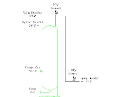
Per the ASME code, the pressure relief device must open at or before any part of the vessel reaches the design pressure. Figure 1 shows the vessel layout with the current pressure relief valve (PRV) location as Option 1 and a new proposed location as Option 2.
The first common misconception often encountered is that a vessel's rating allows operation at the design pressure at the pressure measurement point. This plant mythology is false. The ASME code doesn't specify the location of required pressure measurement points. The code specifies that the system pressure plus the coincident liquid head must be below the vessel design limit at all points on the vessel. For our example, this limit is the lower edge of the feed nozzle at the bottom of the vessel.
The feed nozzle centerline is at 3 ft. 3 in. above grade. The lower edge of the nozzle is 9 in. lower, at 2 ft. 6 in. The PRV currently is located in a piperack downstream of the vessel (Option 1). The PRV inlet is at 12 ft. 0 in. At an operating density of 48.8 lb/ ft3 this gives 5 psi of static head (rounded up). The maximum PRV relief setting is 161 psig (165 psig design limit minus 4 psi static head).
A proposal "to take full advantage of the vessel design pressure" would move the PRV to the Option 2 location. This idea stems from the thought that the vessel's top seam defines the design pressure. This idea is wrong. It's also very curious. Even if you believe that the top seam defines the design pressure, why move the PRV? Just reset it to account for the correct static head.
What must happen if the PRV moves to the Option 2 location? The elevation of the pipe is 67 ft. 4 in. and the PRV inlet is at 69 ft. 0 in. At an operating density of 48.8 lbs/ft3 this gives 23 psi of liquid head (rounded up again). The maximum PRV release setting is 142 (165 psig design limit minus 23 psi static head).
The key point is that pressure relief devices must protect all points of the vessel from exceeding design pressure. Moving PRVs doesn't change vessel design pressures. Always go back to the U-1 forms when you must verify design pressure. Other documentation, while convenient and helpful, remains secondary to the U-1 forms and related vessel code stamps.
ANDREW SLOLEY is a Chemical Processing contributing editor. You can e-mail him at [email protected]


