Our industry doesn't use energy as efficiently as it could, contend some critics. They cite plants that downgrade heat to a cooling utility or provide heat from a heating utility even when temperature levels may indicate the heat can be recovered. These faultfinders don't appreciate the importance of control.
[pullquote]The purpose of any control system is to move a disturbance from where it's undesired to where it's unimportant. Utility systems provide a straightforward and often inexpensive method of absorbing disturbances. As a process becomes more heat-integrated, control becomes more difficult. Inability to control has real costs.
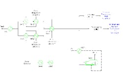
One part of a recent project involved improving unit heat integration. Figure 1 shows a section of the unit before modification. The feed goes through five heating services before heading to trim heating. The trim heating energy ultimately comes from fuel firing. The column bottoms' product goes through four cooling services before trim cooling. The trim cooling duty varied from 50% to 125% of the trim heating requirement. Temperature levels were such that the heat could be transferred with a 25°F approach temperature between the streams. At first glance, this seems an ideal match for heat recovery. So, why wasn't it being done?
One key historical reason is that both streams are fouling — the feed moderately and the bottoms highly. For most fouling services at moderate temperatures economics don't support approach temperatures less than ~35°F to ~45°F. In this case, though, the permitting and regulatory benefits of shutting down a heating service (the trim heating) were attractive.
This still leaves a second issue, control. The feed stream has both minimum and maximum temperature constraints. The necessary surface area for a new heat-integration exchanger to meet the minimum temperature requirement on the feed when fouled will overheat the feed when clean. Some type of control is needed to prevent overheating at start of run.
The bottoms stream has a minimum temperature requirement. This is a problem around 40% of the time because of product specifications. Luckily, one steam generator (X451) is already in service upstream of the proposed exchanger. It supplies steam to dedicated services, so maintaining its duty at a maximum is also important. While not ideal, shifting duty from the steam generator to the new service is acceptable as long as the duty shift is always minimized. Placing the new service after the existing steam generator achieves this goal.
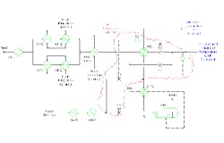
Figure 2 shows the new unit configuration. A bypass loop prevents the feed from becoming too hot at start of run. A second bypass loop on the tower bottoms shifts duty from the steam generator to the new service as required. The exchanger pressure drops set pressure drop available for driving the bypass flow. Under some conditions the heat exchangers have insufficient pressure drop to force enough flow through the bypasses. Two hand-operated control valves enable adding extra pressure drop.
The configuration changes reduce the number of utilities available to absorb control disturbances to one from three. A more complex control system is required to shift the disturbance around the system. Some extra control flexibility comes from allowing the bottoms temperature to rise above minimum values under some conditions.
Flow bypasses provide a simple way to reduce exchanger duty. They also decrease fluid velocity in the exchanger. Low velocity gives higher fouling rates. Using such bypasses can easily create enough fouling to completely negate the benefit of the new exchanger.
To reduce the effect of low velocity and faster fouling, you must adjust the exchanger design by:
• making the pressure drop as high as the system will tolerate on both sides — this keeps the velocities higher;
• using a low-fouling design on the shell-side — in this case, a helical baffle;
• enabling removal of the exchanger from service during operation for online cleaning; and
• employing an easy-to-clean design for the tube side — in this case, a TEMA AET shell to simplify exchanger cleaning.
The final package includes process configuration changes, control upgrades, and special design criteria for the equipment.
Every plant has different constraints, so aggressive energy integration in your facility will pose its own specific challenges. Nevertheless, as you reduce the use of utilities, you will face control issues in nearly every unit. It's essential to track down the consequences of all your changes and address all control challenges.
Andrew Sloley is a Chemical Processing Contributing Editor. You can e-mail him at [email protected].


