Due to pumps we tend to get careless in considering flow systems. A few inches of fluid pressure drop aren’t very important when we shed multiple psi across a control valve. In contrast, without a pump, small pressure drops count. As a result, gravity-flow, free-surface and open-channel systems cause a disproportionately high number of flow problems at plants.
Gravity-flow systems get their driving force from static head of liquid. Free-surface flow includes piping systems where flow rate (usually generated by gravity) doesn’t completely fill a pipe or duct. Open-channel systems are similar except that the flow channel isn’t fully closed.
[pullquote] Let’s examine two common cases that often go together: free draining from a vessel and free surface flow in a pipe.
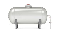
Many vessels have had problems with free-draining connections. Once a nozzle unseals, vapor can enter with the liquid flow. To prevent vapor locking the draw line, liquid velocity must be low enough to allow vapor to vent back into the vessel. Free-surface flow into a nozzle can be very complex. Flow behavior depends upon density difference between vapor and liquid, flow patterns entering the nozzle, velocity of incoming liquid and many other factors. The only sure method to provide free-surface flow is to make the inlet nozzle big enough that some of the more unusual flow patterns don’t get established.
Achieving reliable free-surface flow requires evaluating the flowing liquid’s Froude number. In general this dimensionless number is the ratio of gravity to inertial forces. Gravity (or applied) forces represent energy driving flow while inertial forces (opposing forces) represent resistance to flow.
Fr = V/c (1) where Fr is the Froude number, V is the characteristic velocity of the system, and c is a characteristic wave-propagation velocity. Unfortunately, the exact form V and c take in a specific application depends upon circumstances.
Modifying the Froude number to a dimensionless superficial volumetric flux (J*) suitable for use with venting nozzles we get:
J* = 4Q/[πd2(gd)0.5] (2) where Q is volumetric rate of flow, d is actual inside diameter, not nominal pipe diameter, and g is the gravitational constant, all in consistent units.
Simpson identified a maximum upper value of 0.3 for the Froude number for reliable self-venting flow through a nozzle entering a vertical pipe [Perry’s Chemical Engineers’ Handbook, 8th ed., p. 6-29 (2008)]. This means the outlet nozzle will run less than half full at the nozzle entrance and gives the design equations:
d = 4.27Q0.4 (3) for d in cm and Q in m3/hr, and d = 0.928Q0.4 (4) for d in in. and Q in gpm.
These equations allow us to find the minimum required diameter to reliably get a specific flow rate if the nozzle isn’t fully flooded.
The second common situation involves a partially full near-horizontal pipe. Flow requires pressure drop. In gravity-flow systems pressure drop comes from height of liquid. Partially full pipes must slope to provide height of liquid to drive fluid flow. The question is, how much? Many mechanical and chemical engineers use arbitrary standards. Few of them have heard of the Chezy formula for estimating fluid velocity in a sloped line:
v = (2g/f)0.5(dhs/4)0.5 (5) where v is fluid velocity, f is Fanning friction factor, dh is hydraulic diameter, and s is sine of the slope angle. (The first term is the Chezy coefficient, C.) At a constant slope, s equals the height difference divided by the length of pipe.
For sizes smaller than 6 in., pipe should run no more than 50% full to allow for vapor backflow; for pipes larger than 6 in., most applications can tolerate up to 75%-full pipes. For the relatively short lengths at process plants a 40:1 slope is a good starting point for evaluating piping systems with commercial pipe and low viscosity fluids (e.g., water and light hydrocarbons). If available, steeper slopes allow for smaller diameter pipes.
Use flooded-nozzle sizing to set initial intake size, establish flow with a gradual slope, then increase the slope and smoothly decrease pipe diameter to reduce investment. With large systems, long pipe runs and more complex layouts, some research to decide on hydraulic design will reward your efforts.
Andrew Sloley is Chemical Processing's Contributing Editor. You can e-mail him at [email protected]

