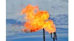
The young engineer I worked with couldn’t fathom why I toiled in the hot sun surveying for a nitrogen skid. No doubt to him my tools — a tape measure, deadweight, plumb bob, chalk and clinometer — seemed anachronisms. But they got the job done. Within 10 days I completed CAD drawings showing above ground and underground piping and relevant equipment. Everyone had said use the existing drawings but none provided complete details. From my drawings, I created six possible scaled layouts and a pro/con table for a meeting that quickly settled the final location. Developing skills in surveying and drafting will help you succeed in any engineering environment. Such skills include: drawing isometrics, plan views, elevations and mechanical details as well as measuring heights of stacks and depths of sumps.Let’s consider isometrics first. An isometric view has length, width and height. It’s really an optical illusion of sorts. There are four possible orientations if we leave the z direction alone. So, the first chore is selecting the best orientation, one that displays pipeline equipment, i.e., valves, pumps, etc., in a clear manner. Try to line things up from an operator’s view. The next decision is: how much detail is needed? A “stick drawing” is simplest and easiest, and generally suffices for field isometrics. For more polished drawings or ones where special mechanical details must be shown, depict pipe size and shape. If you choose stick drawings, you’ll need to identify how pipe spools are connected, typically: flanged, threaded, socket-welded or butt-welded. There are drawing standards: flanges are shown as two perpendicular lines; welded pipe requires an enlarged dot; and threaded spools use a single perpendicular line to the pipe. It’s always a good idea with a new plant to check a few of its process and instrumentation diagrams against the standards. [pullquote] Now, let’s consider plans and elevations. You also can do these in stick form, which, again, is best for field work. In such drawings, point of view (POV) is more critical than for isometrics. A half-filled circle designates a pipe that recedes into the distance, rises or falls; vessels are unfilled circles. A poor POV selection will impede clearly seeing equipment and nozzles. With complicated pipe, break your isometric into several sections of plans and elevations. Mechanical details are necessary to define such things as special fittings and tank nozzles. Early in my career, I designed a prototype for a sensor to catch fragments of metal in our packaging lines. As someone who got a B in high school drafting because I’m a “lefty,” this challenge scared me. I stuck to conventional material dimensions, drew several sections and it worked out. Remember: section arrows point away from POV direction. If they point to right, the cut is shown with a POV looking right. OK, we’re off to the field. Level measurement is fairly straightforward. I usually bring a rock, or deadweight, for the other end of the tape measure. Measuring heights hasn’t changed much since the Egyptians but tools now are easier to use. Modern surveyors employ a device called a theodolite. If you saw “Raiders of the Lost Ark,” you know what an optical theodolite looks like. It’s accurate to about 1–60″ of an arc. Laser theodolites are probably more accurate — but the trouble with a laser is you’ll need a hot permit in a refinery and many chemical plants.All theodolites suffer from one crippling problem: set-up time. Even someone skilled with a plumb bob and level could spend a half-an-hour squaring a theodolite base.I came up with a simple solution: the clinometer. The U.S. Forestry Service uses clinometers to measure tree heights. Error can be less than one foot, which is accurate enough for most process calculations. The geometry only gets complicated if the ground is broken; this usually isn’t a problem in a chemical plant. A clinometer is fast; I’ve made six measurements in an hour.The device consists of an eyepiece with a weighted wheel in a liquid. You measure height by sighting the object from a known distance and using this formula: ho + d × tan(a) = h — where ho is height of the eyepiece from the ground; h is final height; d is distance from the base of the object and a is angle from the ground to the object.So, why do you need measure a height? Can’t you just calculate it from a drawing? Maybe, but the drawing won’t include the concrete pad, etc. If you need accuracy, using a clinometer sure beats climbing to the top of a 165-ft flare stack.Dirk Willard is a contributing editor to Chemical Processing magazine. You can e-mail him at[email protected].


