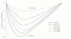
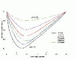
Plants often must move fluid from a large vessel into a pipe. For pressurized systems this rarely creates problems. However, for systems in which static head sets the available head even the small inlet losses from nozzles can restrict flow. So, it’s important to understand flow resistance coefficients (k) in your system to check low head flows. [pullquote]The classic nozzle entrance shape is a flush connection with a k = 0.5. But other shapes abound, e.g.: angled flush, projecting, flush cone, flush bellmouth and projecting bellmouth (Figure 1), as well as screens and perforated plates. When limited by head available from gravity these complex pipe entrances can dramatically change system capacity. The k of these shapes are hard to find. So, here’s a selection of the more useful. [sidebar id="1"]Pressure drop through an outlet pipe is evaluated in height of the flowing fluid (h). The standard equation is: h = k (v2/2g)where v is the velocity of the fluid and g is acceleration due to gravity. Converting this to a dimensional equation gives the two forms commonly used: h = 522 (kq2/d4) = 0.00259 (kQ2/d4) where q is flow in ft.3/sec., Q is flow in gal./min., d is diameter in inches and h is height in feet. If you know k, you can easily calculate head losses for piping entrances. I. E. Idelchik’s “Handbook of Hydraulic Resistance” provides k values. Unfortunately, working with that book poses challenges. The text was complex to begin with — garbled translation coupled with missing subscripts in some equations and use of the wrong symbols in others require the reader to take extreme care. It’s not 100% clear from the text but Idelchik seems to have force-fitted his curves to meet theoretical boundary-limit conditions for known special flow cases. This leads to some apparent contradictions in k values that aren’t immediately obvious in the published k graphs. Despite these problems Idelchik is still the best one-stop reference for k. (Checking published values in supposedly authoritative sources deserves a future column.) For angled flush entrances: k = 0.5 + 0.3 cos θ + 0.2 cos2 θ[sidebar id="2"]Figure 2 graphs k for bellmouth or rounded entrances. The boundary limit for a bellmouth entrance is a radius-to-diameter (R/D) ratio of zero, which equates to a sharp-edge entrance. “Crane Technical Paper 410 — Flow of Fluids through Valves, Fittings and Pipe” only provides a value (k = 0.78) for a sharp-edge entrance for a freestanding or projected entrance. In comparison, Idelchik gives the entire curve but with a 1.0 value for a sharp-edge entrance. Its k values are higher for the freestanding entrance because they’ve been force-fit to boundary conditions of an infinitely thin pipe. Crane’s values stem from experiments with relatively thick commercial pipe; the thick pipe entrance reduces the effect of inlet losses. The Crane tables also show an unexpectedly low k when R/D = 0.02. Figure 3 shows k for flush conical or countersunk entrances. Here, you must specify both the cone’s angle and length/diameter (L/D) ratio. Flow resistance approaches a minimum between 40° and 60° depending on the relative depth of the cone.
Figure 3. Flush conical entrance: Values
depend on cone angle as well its
length/diameter ratio.
Click on image to enlarge.
Dhydraulic= (4 × flow area of opening)/(wetted perimeter of opening)
These curves and equations enable estimating losses for many of the more common shapes of piping entrances. For extremely complex flow configurations as well as laminar and transition flow regimes, go to the standard references to find what you need. But double-check the assumptions behind the values and understand how they apply to your situation.
Andrew Sloley is a Chemical Processing contributing editor. You can e-mail him at [email protected].
Sponsored Recommendations
Sponsored Recommendations
Latest from Fluid Handling
Latest from Fluid Handling
Sponsored
Sponsored


