Proper plant operation often depends upon effective control of steam-heated shell-and-tube exchangers. Two previous articles (see sidebar) examined control of the liquid outlet temperature using a control valve on either the steam supply or the condensate return. This article will focus on cascade control configurations for these two cases. A future article will look at liquid bypass arrangements.
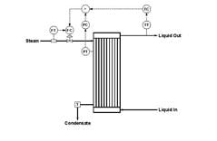
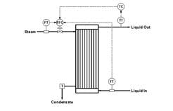
Figure 1 depicts simple feedback and temperature-to-flow cascade configurations for controlling liquid outlet temperature using a control valve on the steam supply. With the advent of digital systems, the use of cascade configurations significantly increased. The only additional hardware for implementing the cascade configuration is a measurement device for steam flow. All other components are implemented in software.
To distinguish between the two loops, we’ll use the terms “inner” and “outer.” For the temperature-to-flow cascade, the flow loop is the inner (or “slave”) loop and the temperature loop is the outer (or “master”) loop.
Figure 1 --Valve on steam supply:
Two approaches can provide liquid
outlet temperature control via a
valve on the steam supply.
Click on illustration for larger image.
Cascade configurations usually are justified on improved dynamic response to disturbances to the inner loop. Suppose significant variations occur in the steam supply pressure. For the simple feedback configuration (Figure 1a), the temperature controller wouldn’t respond until the change in steam supply pressure affects liquid outlet temperature. But for the cascade configuration (Figure 1b), the flow controller responds when the change in steam supply pressure affects steam flow. The cascade configuration would respond to this disturbance far more rapidly than the simple feedback configuration.
For a cascade configuration to properly function, the inner loop must be faster than the outer loop — the general guideline is at least five times faster. For most temperature-to-flow cascades, the dynamic separation between the loops would exceed 5:1.
However, as temperature loops go, the liquid outlet temperature loop responds quite quickly. Furthermore, a common practice is to very conservatively tune flow loops. Typical suggestions for the tuning coefficients include the following:
Figure 2 -- Process operating line:
Temperature-to-flow cascade control
provides an essentially linear
operating line.
Click on illustration for larger image.
1. controller gain 0.1%/%; reset time 2 sec.;
2. controller gain 0.2%/%; reset time 3 sec.; and
3. controller gain 0.3%/%; reset time 5 sec.
In practice, these settings give about the same performance. They’re also very conservative. If the flow controller doesn’t function with one of these settings, the first step should be to understand why.
Flow loops are so fast that even conservative tuning provides acceptable performance, with little or no incentive to improve performance of the loop. However, this isn’t necessarily the case for the temperature-to-flow cascade. Because the liquid outlet temperature loop is relatively fast for temperature loops, a conservatively tuned steam flow loop might not be five times faster than the temperature loop. So, if you experience difficulties tuning the temperature loop, consider more-aggressive tuning in the steam flow controller.
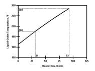
For the primary controlled variable, the process operating line for cascade control often markedly differs from that for simple feedback control. Figure 2 shows the operating line for liquid outlet temperature controlled via a temperature-to-flow cascade. Because the output of this temperature controller is the set point for the steam flow controller, the operating line presents the liquid outlet temperature as a function of steam flow.
The operating line is essentially linear. Furthermore, it’s unaffected by the inherent characteristics (linear, equal-percentage or other) of the steam valve. The flow controller has to contend with all issues associated with the valve. In effect, the flow controller isolates the temperature controller from such issues.
The PID controller is a linear controller. With a linear process operating line, the process is linear (at least for a given throughput). Consequently, a given value for the controller gain will deliver consistent performance for all steam flows. In some exchanger applications (but not most), this could be a major advantage, making the outer loop far easier to tune in the cascade configuration that the corresponding loop in the simple feedback configuration.
Minimum Heat Transfer Rate
The operating line in Figure 2 suggests that the minimum steam flow is approximately 31 lb/min. This corresponds to a steam valve position of 29% (equal-percentage valve), a liquid outlet temperature of 200°F and atmospheric pressure in the shell of the exchanger.
The cascade configuration can suffer the same cycling described in the first article in this series for the simple feedback configuration. This phenomenon reflects the characteristics of the process. The process just isn’t capable of smooth operation at lower heat-transfer rates. Control system sophistication can’t address this problem nor can it be “tuned out.” However, it’s reasonable to expect that the controls recognize the limits of process operation and not attempt to operate beyond those limits.
Figure 3 -- Shell pressure override:
For a temperature-to-flow cascade,
use the output of the high select as
the set point of the steam flow controller.
Click on illustration for larger image.
Based on the operating line in Figure 2, the temperature loop shouldn’t specify a steam flow set point less than 31 lb/min. In digital systems you easily can place limits on the set point for the inner loop of a cascade; such systems also will address the windup issues in the outer loop of the cascade. The shortcoming of this approach is that the value of 31 lb/min for the minimum steam flow isn’t precise and also depends upon process variables such as the throughput.
The first article in this series proposed a shell pressure override loop for the simple feedback configuration. A temperature-to-flow cascade also can incorporate a shell pressure override (Figure 3) — the output of the high select serves as the set point of the steam flow controller. Otherwise, the issues are the same. Implementing this configuration requires an additional measurement device for shell pressure. For exchangers that discharge condensate to a drain, the set point for the shell pressure controller would be slightly above atmospheric. For exchangers that discharge into a condensate return system, the set point must slightly exceed the pressure required to force the condensate back to the boiler house.
Maximum Heat Transfer Rate
The operating line in Figure 2 suggests that the maximum steam flow is approximately 93 lb/min. This corresponds to a fully open steam valve, resulting in a liquid outlet temperature of approximately 290°F and a shell pressure essentially equal to the steam supply pressure.
Figure 4 -- Functional but sluggish:
Condensate control works but very
slowly compared to most flow loops.
Click on illustration for larger image.
Allowing the liquid outlet temperature to specify a steam flow set point in excess of 93 lb/min would result in windup in the liquid outlet temperature controller. You could impose a maximum limit on the steam flow set point, but there’re better methods for preventing windup:
External reset. The measured value of steam flow is the external reset input to the liquid outlet temperature controller.
Integral tracking. When the steam valve opens fully, the measured value of steam flow is used for the integral term within the liquid outlet temperature controller.
Inhibit increase/inhibit decrease. When the steam valve opens fully, the liquid outlet temperature controller isn’t allowed to increase the steam flow set point.
These methods have the additional advantage that you needn’t precisely know the maximum steam flow. Although some digital systems provide more than one of these options, any will suffice.
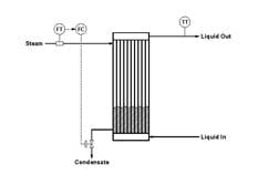
The flow controller in Figure 4 regulates the steam flow by manipulating the control valve on the condensate. Changing the condensate valve opening affects the condensate level within the exchanger, which affects the heat transfer area exposed to the condensing steam, which affects steam flow. This loop will function but its dynamics are far slower than those of most flow loops.
Figure 5 -- Valve on condensate:
Simple feedback may outperform cascade
for liquid outlet temperature control
via a valve on the condensate.
Click on illustration for larger image.
I previously recommended some settings for a flow controller — these come with one condition: the flow measurement must directly sense the flow through the control valve. This is the case in Figure 1b with the control valve and flow measurement in the steam supply but not in the configuration in Figure 4, where steam flow is measured but condensate is flowing through the control valve. At equilibrium, the steam flow must equal the condensate flow, but the two can significantly differ during transient conditions. So, the recommended settings won’t work for the configuration in Figure 4.
Having established that we can control the steam flow using a valve on the condensate, let’s now consider the temperature-to-flow cascade configuration illustrated in Figure 5b. Because condensate flow (in lb/min) must equal steam flow (in lb/min) at equilibrium, the process operating line for the control valve on the condensate is the same as the process operating line for the control valve on the steam, but with one exception: the minimum steam flow is zero when the control valve is on the condensate whereas the minimum steam flow is 31 lb/min when the control valve is on the steam. The maximum steam flow is exactly the same for the two configurations. With the control valve on the condensate, the process operating line is essentially linear from a steam flow of zero up to the maximum.
The cascade configuration in Figure 5b presents the problem that it can’t guarantee the required 5:1 separation of dynamics between the two loops of the cascade. When the condensate valve is used to control steam flow, the dynamics of this flow loop are far slower than that of most flow loops. In addition, the dynamics of the liquid outlet temperature loop for the exchanger are much faster than the dynamics of most temperature loops. So, it’s unlikely that the flow loop will be five times faster than the temperature loop. You’ll be able to tune the flow loop but will experience difficulties in tuning the temperature loop. The only way to get the temperature loop to operate on automatic is to use very conservative settings (low controller gain, long reset time) that make the loop respond very slowly. The simple feedback configuration in Figure 5a will perform better than the temperature-to-flow cascade in Figure 5b.
Figure 6 -- Process operating line:
For temperature-to-flow cascade,
as throughput increases gain or
sensitivity decreases.
Click on illustration for larger image.
Variable Throughput
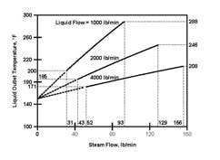
Figure 6 depicts the process operating lines for various throughputs for the control valve on the steam supply. The operating lines are identical except that the minimum flow is zero for the control valve on the condensate.
At a given throughput, the process operating line is essentially straight. The slope of the operating line is the process gain or sensitivity. The exchanger typifies most processes in that as the throughput increases the gain or sensitivity decreases.
Processes with variable throughput raise some tuning issues. You must tune the liquid outlet temperature controller at a low throughput, where the process sensitivity is the highest. However, as the throughput increases, the process sensitivity decreases, which will lead to a slower-responding loop. If a measurement of liquid flow rate is available, you can use scheduled tuning to increase controller gain with liquid flow.
However, if you have a liquid flow-rate measurement, the temperature-to-flow-ratio configuration (Figure 7) is a better approach. It uses a flow-to-flow controller (FFC) or a flow ratio controller. One input is the liquid flow rate, which is referred to as the “wild flow,” because either upstream or downstream processes determine this value. The other input is the steam flow, which is referred to as the “controlled flow,” because the position of the steam control valve governs its value. The set point for the flow-to-flow or ratio controller is the desired ratio of steam flow to liquid flow. The output of the liquid outlet temperature controller is this set point.
For the temperature-to-flow-ratio cascade, the process operating line is a plot of the liquid outlet temperature as a function of the steam-to-liquid flow ratio. This plot will be a straight line whose slope is independent of the throughput. The temperature-to-flow-ratio cascade will respond quickly to changes in liquid flow rate (and also quickly to changes in steam supply pressure). The temperature controller must respond to other disturbances such as changes in the liquid inlet temperature. But, because the operating line is linear and independent of throughput, it will give a consistent response.
Figure 7 -- Better approach:
If a liquid flow-rate measurement
is available, use temperature-to-flow-ratio
cascade.
Click on illustration for larger image.
With the control valve on the steam supply, issues regarding the minimum and maximum possible heat transfer rates also apply to the temperature-to-flow-ratio cascade:
Minimum steam flow. If the shell pressure drops below that required for the condensate to flow out of the exchanger, the cycling situation described in the first article will occur. This is best prevented by measuring shell pressure and incorporating a shell pressure override on the output of the liquid outlet temperature controller.
Maximum steam flow. If the flow-ratio set point is too high, the resulting steam flow will exceed the maximum possible steam flow. This raises the potential for windup. So, incorporate one of the three suggested windup-prevention methods into the configuration of the temperature-to-flow-ratio cascade.
A temperature-to-flow-ratio configuration also is possible where the control valve is on the condensate.
However, the issues are the same as for the temperature-to-flow configuration discussed previously. The steam flow responds slowly to changes in the condensate flow. Consequently, the flow ratio controller will respond slowly. With the valve on the condensate, the ratio configuration can’t respond effectively to rapid changes in the liquid flow. And, as before, the configuration can’t provide the necessary 5:1 separation in dynamics between the temperature loop and the flow ratio loop.
Cecil L. Smith is president of Cecil L. Smith, Inc., Baton Rouge, La. E-mail him at [email protected]. He is the author of “Practical Process Control,” which John Wiley is publishing early this year.


