Better understanding boosts mixer scale-up
|
Related articles Don’t get mixed up by scale-up Mind mixer mechanical design |
Despite an increasing number of theories and equations in the public domain, there really isn’t a golden rule to successful scale-up. The issues involved are so diverse with so many variables that no one rule can be applied. Even classifying the equipment used under the umbrella term “mixer” can be complex.
So first, let’s distinguish between an agitator and a mixer. Agitators employed in a vessel to promote heat transfer, maintain bulk movement or provide in-tank uniformity often are considered to be “process aids” rather than mixers. (Pumps in this respect fall into the same classification because their function is merely to move the product rather than to alter it.) In contrast, mixers combine two or more ingredients, bringing about a change in these ingredients during the formation of the end product through several operations that may include particle size reduction, homogenization, emulsification, reaction acceleration and so on — many of these may be occurring at the same time in a single operation; a range of operational or hydrodynamic variables may apply in any given service.
For agitators (and pumps), because they’re carrying out relatively simple tasks, it’s possible to forecast with a high degree of certainty the size and configuration of the machine required for a particular application. Technical advances such as Computational Fluid Dynamics (CFD), Laser Doppler Anemometry (LDA) and Particle Induced Velocimetry (PIV) are helping make the task easier. They enable modeling the performance of equipment, even taking into account vessel and impeller geometry, batch size and product characteristics — providing sophisticated and accurate scale-up information without necessarily having to carry out any physical testing.
For high shear mixers such as rotor/stator devices the tasks are more demanding — for example, forming an emulsion or suspension, reacting two ingredients together, etc. — and, so too, is accounting for the varied operations occurring, often simultaneously. The mixers’ versatility means that more complex factors are involved, making it more difficult to understand and predict what’s going on and what will happen under certain conditions. So, selecting a single criterion as a basis for scale-up calculations is far too simplistic an approach.
Scale-up considerations for rotor/stator mixers go beyond just sizing the equipment; selection of workhead or stator screen configuration can significantly impact end results in terms of process times, quality of finished product and so on. In addition, it’s important to consider the physical properties of the materials, for example, whether the rheology of the product is affected by shear forces and changes in temperature. Scaling-up from lab trials to specify the correct production unit requires that all calculations be tempered by experience — it’s this “educated guess” that’s the key to successful scale-up.
Going beyond “guessology”
With high shear mixers, laboratory scale units tend to closely resemble their production counterparts in design but their speeds (and rotor tip speed is what’s important here) often are far higher than on the larger units. So, interpreting results requires a degree of experience. A rule often applied at the start of testing is that if the task can be completed on the lab scale relatively quickly it can be replicated in bulk manufacture — but it follows that if poor results are obtained at this initial stage simply hitting the problem with larger, more powerful equipment may not be the answer.
Once laboratory scale testing has established the viability of the task, calculations for sizing the right mixer for an application typically are carried out based on vessel geometry and required throughput for in-line devices or tank turnover rate in terms of immersion machines, which reflects the common need by end users to achieve a result in a given timescale. These calculations are made with allowance, based almost entirely on experience, for the characteristics of the product being mixed.
This guessology has worked well enough for many years. Increasingly however, end users of the equipment expect a level of technical data to be provided — as is the case with agitators — to allow them to make better informed decisions when specifying a mixing system. Technical data sheets more and more frequently accompany quotations for new machinery and equipment manufacturers often must assist with validation and the provision of process guarantees.
Figure 1. It’s usually prudent to run trials of materials on lab or production scale units
at a vendor facility.
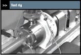
Figure 2. High shear in-line test rig at Cranfield includes transducers for torque and
differential pressure. Source: British Hydromechanics Research Group.
In addition, some mixer manufacturers have been working with academic organizations to further the understanding of the processes involved in high shear mixing. To date limited research has been carried out in this field and still less has been published. Only a couple of institutions have turned their attention to the subject — namely the University of Maryland, College Park, Md., with its High Shear Mixing Research Program, and the British Hydromechanics Research Group at Cranfield University, Cranfield, U.K. (Figure 2). Because this research has been carried out by consortia that includes equipment manufacturers, much of the data remain within their control. Again, results from these studies are being utilized to streamline development processes and as an aid to scale-up but little of the research has found its way into the public domain. To some extent this is understandable because the market for high shear mixing equipment is relatively small and highly competitive. The ability to accurately scale-up when specifying mixing equipment for a given application is one of the suppliers’ competitive advantages; the application of new techniques in combination with many years of research and development is a vital part of this advantage.
Scale-up calculations
Figure 3. This unit features fine emulsor screens with circular holes but a variety of other hole types are available for other applications.
Energy dissipation. In a situation where vessel and mixer geometry are similar across a range of sizes, energy dissipation is considered to be constant and, therefore, a useful tool in scale-up calculations. Power has to be monitored while mixing to determine the effects of the fluid’s physical properties on power draw. The most reliable way of doing this is to incorporate a torque transducer onto the mixer’s shaft to measure the total energy, ε, supplied to the mixture. This is estimated by the formula:
ε = P fluid/V (1)
where V is the volume of the mix (m3) and PFluid is the total power expended to the fluid (W), calculated from torque data as P = 2πNT, with N being the rotational speed (rev/s) and T (N.m) the torque value.
Rotor tip speed. Vtip (m/s) can be used to assess the kinetic energy imparted to the process fluid from the tip of the rotor blade as well as in calculating the shear stress and rates imparted to the fluid:
Vtip = πND (2)
where N is the rotational speed (rev/s) and D is the rotor diameter (m).
Tip speed plays a major role in determining the shear rate in the gap between the rotor and stator, γgap (s-1). This is where shear rates are maximized, therefore quantifying the activity in this region is of considerable importance in predicting the performance of equivalent machines across a range of sizes in scale-up. We can estimate the value for the shear rate in the shear gap via:
γgap = Vtip/δ (3)
where δ is the shear gap (m).
The γgap will become more significant at higher viscosities because the velocity gradient will increase. At lower viscosities the flow patterns in the gap won’t exhibit simple shear flow and will become more turbulent — in which case turbulent energy dissipation may become more significant.
Although scale-up using values of shear rate and tip speed work well in some applications involving agitators and stirrers, they aren’t necessarily always applicable to rotor/stators. The reason is that the flow from the workhead is assumed to travel at the same speed as the rotor tip. It then undergoes a sudden slowdown as it impacts the stator wall; the losses in kinetic energy during this process (hydraulic shear) contribute to functions such as dispersion and emulsification. Therefore, the tip speed in combination with the rotor/stator geometry (and physical properties of the fluids) will have a more significant bearing on scale-up issues than tip speed alone. These factors combined form another parameter, called the shear frequency (sf), that is commonly employed in these calculations.
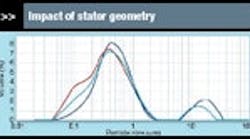
Figure 4. Titanium dioxide slurries from square hole high shear screen (red line)
and slotted head (light blue line) differ in particle size distribution from control
sample (dark blue line).
Lee et al. in a 2004 article “Rotor-stator milling of APIs…” in American Pharmaceutical Review discussed their use of shear frequency as a scale-up option in wet milling applications. When studying the milling of active pharmaceutical ingredients, they found that the shear frequency doesn’t affect the minimum achievable particle size but that it aids the rate of particle size reduction. Shear frequency is expressed as:
sf = NnRnS (4)
where nR is the number of blades/teeth on the rotor and nS is the number of holes/slots on the stator.
Residence time is an important scale-up parameter because the break-up of both particles and droplets is time dependant — they will break only if they’re exposed to the high shear/energy areas for a sufficient amount of time. In considering this parameter, a rotor/stator mixer can be divided into the following sections, listed in order of decreasing residence times: (a) the shear gap, (b) the stator region, (c) the rotor region (volume of openings in the stator), and (d) the volute.
It’s important to note that increasing the residence time in the gap by making it larger won’t increase the areas of high energy because the flow interactions between the rotor and stator remain constant. Increasing the number of holes or slots will increase the rotor/stator interaction and, in turn, increase the number of high energy regions. This can be accomplished by changing the screen, a relatively easy operation and one of the main selling points of the rotor/stator design. The effect on rotor and screen configuration on shear values also has led to the rise of multi-stage mixers (consisting two, three or more rows of concentrically arranged rotors and stators). Coupling the estimation of nominal residence times with a Reynolds analysis, where the Reynolds number is the ratio of turbulent forces to viscous (laminar) forces present in a system, makes it possible to investigate whether inertial (turbulent) or viscous (laminar) forces are likely to control mixing in each of the regions.
Figure 5. CFD diagram helps predict potential wear patterns when scaling-up a 8-in. rotor/stator in-line mixer (top) to a 10-in model (bottom).
Understanding the flow patterns within each of the regions of the rotor/stator mixer provides an appreciation of the areas of high energy dissipation and the types of breakup mechanisms that would be induced as a result. The High Shear Mixing Program has employed techniques such as CFD, LDA and PIV to observe and replicate or model the complex flows in the rotor/stator in-line mixer. In a commercial application, an equipment manufacturer (Silverson) and a client conducted a joint study using CFD modeling to predict the wear potential on an in-line mixer processing a highly abrasive ilmenite slurry (Figure 5). The need to increase throughput required upgrading the mixer from a unit with an 8-in. rotor to a 10-in. model. Sizing the mixer to achieve the increase was effectively an everyday calculation; the CFD modeling allowed an accurate assessment of the impact of this change in internal geometry on the abrasive forces within the mixing zone and provided the basis for design alterations to overcome this problem.
Progress but no simple solution
It’s clear that scale-up of rotor/stator mixers depends on more than one factor and the development of a clear set of rules isn’t straightforward. In the past, attempting scale-up based on a single parameter often led to erroneous results and discrepancies in performance. Fortunately, practical testing has come a long way from the “trial and error” approach employed when this technology first emerged over sixty years ago. The increasing use of instruments such as particle/droplet size analyzers, viscometers and rheometers to quantify the effects of the mixer significantly aids this process, as do capabilities such as for monitoring power draw during trials. Some new generation laboratory scale units incorporate advanced levels of instrumentation as standard; similarly, test facilities now allow monitoring a range of operating conditions when trialing production scale units. As a result, a well-resourced laboratory facility is vital in the process of rotor/stator mixer design and specification. The various academic and research institutes that are carrying out studies into rotor/stator mixers typically employ a combination of practical testing and computational and physical modeling to quantify the effects of various factors.
Nevertheless, the wide range of applications these mixers serve makes the identification of important parameters a daunting task. Although considerable progress has been made, there’s still much work to be done. The current level of knowledge allows the streamlining of pilot plant trials when specifying a mixer but doesn’t eliminate the need for them. From a mixer manufacturer’s perspective, acquired experience remains the key tool in designing and specifying a mixer. This allows the vendor to make recommendations taking into account a wide range of other real-world factors, including variations between formulations or raw materials, limitations in installation within existing processes and complications due to particular vessel geometry — factors that can’t be accounted for by theoretical means. But the increasing emphasis on an empirical approach to back this up is making the science — or art — of guessology a more precise option.
Chris Ryan is a technical advisor at Silverson Machines Ltd., Chesham, U.K.
E-mail him at [email protected].
Niraj Thapar is a former Silverson R&D engineer.
