The steam trap is a small, inexpensive component in steam plants. What they lack in size, they make up for in numbers. In a typical steam plant their numbers range from several hundred in a large industrial steam plant to more than 20,000 in refinery or chemical complexes. Because of their ubiquitous nature, steam traps never received sufficient attention from most energy managers or system designers until the energy crisis of the 1970s.
According to the American Society of Mechanical Engineers (ASME), the first steam trap, a floating head design, was invented in 1835. This early steam trap separated valuable, live steam from condensate, thus reducing the danger of water hammer in building heating systems. The modern float, fixed orifice and bucket steam traps were developed in the early 1900s. Though an improvement over their early ancestors, they were bulky, heavy and expensive. These traps operated on the principle that steam is a gas and condensate is a liquid. Traps like these are still used today and have changed little from their original design. Major changes in steam trap design started with the development of the thermostatic and thermodynamic traps. One of the first patents for the thermostatic design was registered by C.A. Dunham around 1900.
The evolution continues today with the advanced features to improve energy efficiency. A new generation of traps is available combining the characteristics of bimetallic, thermostatic and thermodynamic designs. The selection of a trap for a given service must consider many factors that require the knowledge of trap manufacturers, researchers and other power plant engineers. What features make the perfect steam trap? There are several key design features to look for when selecting the steam trap best suited for each application:
- No tolerance for lost steam under all operating conditions;
- Rugged construction with low maintenance costs;
- No disruption of operations if the trap fails;
- Self-draining to prevent damage from freezing during plant shutdown;
- Minimized valve seat wear;
- “All-in-one design,” with a strainer, check valve and air vent;
- Efficient temperature control through effective condensate discharge; and
- Fast plant start up with continuous venting of air and CO2.
Some of these features are critical such as no steam loss during process operation. Others, such as an all-in-one (integral) trap, usually fall in the category of nice-to-have. This isn’t always true. Such a characteristic may become extremely important if the trap must fit into a tight corner. The ranking of these features is part of the selection process.
In the process of trying to simplify their choices in steam traps, many plant engineers are making the selection based only on the purchase price of the actual trap, not the overall cost. The cost of the steam trap will include the additional parts required for piping and the cost of wasted energy (steam loss) during its operating life. Traps that address these issues will reduce the overall cost of installation and maintenance.
There is more to choosing a steam trap than calculating the load. Conditions vary, but it’s common for traps to be exposed to stresses of a chemical, thermal and mechanical nature. Corrosion from the action of oxygen and carbon dioxide in the condensate attacks the piping interior surfaces. Erosion from blast effect in intermittently discharging traps can speed up corrosion in return lines. Thermal effects include damage from freezing in cold weather and wide ranges in temperature changes during trap operation. Contamination from solids can restrict the movement of mechanical linkages or block orifices and vent holes. Mechanical vibrations transmitted through the piping or slugs of water traveling down the pipeline at high speeds (water hammer) can easily damage certain types of traps.
Which type of trap is better at meeting these ideal performance goals, resisting harmful plant conditions and providing an overall lower cost? To help make that decision, consider the advantages and disadvantages of the most common traps available today. Understanding the operating principle of steam traps will help.
Float and thermostatic
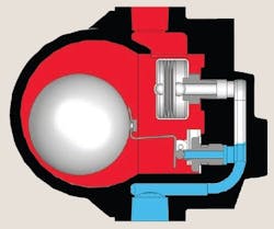
The F&T trap follows the condensate level in the chamber to open the discharge valve (Figure 1).
Figure 1. The float and thermostatic steam trap is sensitive to freezing and water hammer.
A modulating action is produced by the increased opening due to the rising level in the chamber, but the hot and cold capacities are the same. A built-in thermostatic element purges air and gases and closes off when steam enters the trap. Rapid response to changing load is possible, but as operating pressure increases, valve size must be reduced because the buoyancy force from the float is fixed.
The volume of condensate necessary to operate this trap is sensitive to freezing and the float can be damaged by water hammer. This type of trap is large and heavy and must only be mounted in the horizontal position. Main applications are process and space heating where condensate loads are light-to-medium at lower pressures. No strainer or check valve is required, but steam loss can result if internal air vent fails.
Inverted bucket
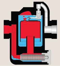
Condensate flows around the bucket to discharge through the valve (Figure 2).
Figure 2. The inverted bucket trap is the workhorse of large process units.
The steam following this condensate fills the top of the bucket, which rises to close the valve due to its buoyancy. Steam escaping through a bleed hole in the bucket and condensing in the body causes loss of buoyancy allowing the bucket to fall and overcome the pressure valve. The action is cyclic with steam loss from the condensing action each cycle.
The volume of condensate necessary to operate this trap is sensitive to freezing and the bucket can be damaged by water hammer. The inverted bucket trap has some versions that are light and compact, but it must only be mounted in the horizontal position. Main applications are process, drip leg and heating. Individual traps only handle a narrow range of pressures. No strainer or check valve is required, but a separate air vent or bypass may be necessary.
Disc
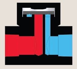
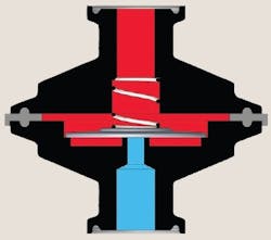
As condensate is fully discharged on startup, steam enters the trap and the flow velocity under the disc rapidly increases (Figure 3).
Figure 3. The disc steam trap is compact and light and often a throw-away trap.
This reduces the pressure below the disc and pulls it down to close the trap. When the steam locked above the disc cools and condenses, it loses closing pressure and allows the cycle to repeat. The action is cyclic with some steam loss from each cycle.
The disc trap is compact and light, but horizontal mounting is preferred. Main applications are small process, drip leg and tracing. No check valve is required, but a strainer and a separate air vent may be necessary. Air can be trapped above the disc, locking the trap in the closed position. The use of a bimetallic ring to hold up the disc during start-up has been tried with limited success. Increased cycling can result when the trap is exposed to cold weather. Dirt can increase steam loss and disc wear, but freezing and water hammer aren’t problems.
Bellows
Alcohol/water mixture sealed into a bellows vaporizes as condensate approaches saturation temperature (Figure 4).
Figure 4. The bellows trap is a good choice for vertical orientations.
The resulting expansion of the bellows closes the valve. Vaporization temperature increases as operating pressure compresses the bellows, in a rough approximation to the steam curve. This results in a cyclic action that modulates from a minimum opening on very light load conditions to full opening at maximum load.
The bellows trap is compact and light and can be mounted in any position. Main applications are small process, tracing, radiators and general. No strainer or check valve is required. Freezing is no problem, but water hammer can fracture the bellows resulting in heavy losses of steam.
Capsule
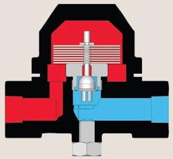
Operation is the same as for bellows, but the alcohol/water mix is contained within a small, wafer-like element to reduce the motion and improve cycle life (Figure 5).
Figure 5. The capsule steam trap, a hybrid of the bellows, can serve in vertical installations.
The action is cyclic, with steam loss each cycle from the blast discharge. Dirt in this short travel valve can cause steam loss.
No check valve is required, but a strainer may be necessary. The capsule trap is compact and light and can be mounted in any position. Main applications are tracing and drip leg. Freezing is no problem and with the “bellows” reduced to a single thin convolution, the risk of water hammer damage is greatly reduced.
Bimetallic-thermostatic
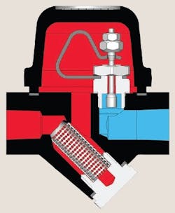
Temperature sensitive bimetal stack closes the valve (Figure 6).
Figure 6. The bimetallic-thermostatic trap is good for small, dirty applications.
This trap is individually adjusted to close at a fixed temperature, making it restricted to a narrow operating pressure range unless re-adjusted. The action is modulating, with good cold capacity and fair hot running capacity. This trap is steam tight at set pressure only, blowing steam to low pressure startup or reduced-pressure operation.
A check valve and strainer may be necessary. This type of trap is compact and can be mounted in any position. The main application is tracing. Freezing is no problem, but dirt and wear in the bimetal stack cause erratic response and changes in performance.
Bimetallic-thermostatic/thermodynamic
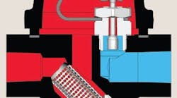
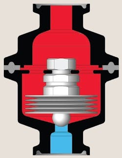
A third generation design, the operation is the same as bimetallic-thermostatic, except a single delta-shaped element is used (Figure 7).
Figure 7. The bimetallic-thermostatic/thermodynamic trap is good choice for compact, difficult-to-classify applications.
This design provides additional thermodynamic flow forces, developed in the downstream expansion chamber, to improve the hot discharge capacity right up to saturation temperature.
No strainer or check valve is required. This kind of trap is compact and can be mounted in any position. The main applications are drip leg, process, heating, tracing and general. Freezing is no problem and the single piece, bimetallic stainless steel element isn’t affected by dirt or wear.
Thermostatic type traps are often considered a universal steam trap, but no single type of trap is ideal for all applications. Ignoring the variety of choices available to simplify this decision can increase the true cost of the steam trap. Steam trap manufacturers can give more detailed information on the operating characteristics and total cost of each type. It’s important to remember that the price of a steam trap includes the cost of installation, maintenance and wasted energy during its operating life.
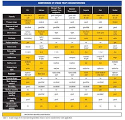
Now that we have reviewed the operating principles, let’s consider the application. Table 1 gives an overview of the various operating characteristics that each trap exhibits and can help to select the best trap design for each application.
Table 1. A wide range of 1st, 2nd and 3rd generation choices can be considered for each application. (Click to enlarge.)
Equipment capital costs, installation and piping requirements, steam trap size and capacity, and ease of maintenance are a few of the factors that influence steam trap selection. The relative cost of the trap designs are shown on the chart. It is typically recommended to include a strainer and check valve (if backpressure is present) with each trap whenever possible. Traps whose design includes these items as standard or as an integral option will reduce installation cost. Traps with replaceable seats can extend the life expectancy with little additional cost. Selecting a trap with more moving parts can increase maintenance cost. There are additional factors that can influence trap selection.
Load
The sizing safety factor of some traps (F & T and bucket) is large because the trap has a fixed orifice whose size is determined based on a small pressure range. Cold start up loads can be 10 times the hot loads present at saturated steam temperature. The larger trap size needed for startup can make initial costs much higher. Piping a manual bypass around the trap can reduce the size required, but the initial installation of extra components is higher; operating the bypass adds to the stack of headaches you normally endure during a start-up.
Dynamic operating conditions
Systems that are frequently shut down can accumulate large amounts of water which must be drained through the trap when steam is turned on. The inverted bucket traps shouldn’t be used in systems that are frequently in and out of service. Inverted bucket traps must be primed (filled with water) before they are put into service. If this procedure isn’t followed, the float mechanism will fail and the trap will pass live steam (fail open). Bimetallic traps don’t respond quickly to changes in load or pressure because the bimetal is slow to react to variations in temperature. Float-and-thermostatic traps are best suited for applications that are frequently in and out of service and require immediate discharge of varying loads of condensate.
Service environment
Where a steam trap must operate can affect its performance. As a rule of thumb, don’t use inverted bucket, F & T or free-float traps at extremely cold temperatures. Residual condensate inside the trap may freeze (and expand) and damage the steam trap body. Disc traps shouldn’t be used in systems that pass a lot of dirt, air or are frequently in and out of service. Avoid using disc traps in systems that are exposed to rain or snow, as these conditions cool the steam above the disc too quickly, and as a result, the trap parts prematurely wear. In inverted bucket traps, the critical components and the orifice are located at the top of the trap. For this reason, the inverted-bucket traps are best suited for applications with excessive chemical usage, pipeline scale, or where rust or dirt is present in the steam line.
Traps used in dirty environments need to have dirt and scale flushed out to prevent them lodging in the trap’s seat. Traps that offer integral blowdown valves reduce installation and maintenance costs and will extend trap life. Blowdown valves are typically attached to strainers, so for traps without a strainer option the blowdown valves and strainer must be installed in the piping separately. Many plants don’t have a steam trap repair and maintenance program. A majority of plants do not know how may traps they have or where they are located. Steam systems that don’t have trap maintenance, over a period of three to five years often find 15% to 30% of their traps have failed. While some trap designs need less attention than others, no trap can be expected to operate forever without any maintenance.
Orientation
Bellows, capsule and bimetallic traps are natural air vents and can be installed in any position. The bellows trap's smooth modulated discharge allows for better performance in process, sterilization and sanitary applications where temperature consistency is critical. F&T traps offer the benefits of both mechanical and thermostatic technologies. The orifice is positioned low on the trap body, creating a liquid seal and improved steam retention. F&T and inverted bucket traps must be mounted in the horizontal position to operate properly.
Efficient steam management
The placement of steam traps in strategic locations throughout the distribution system can be just as important as selecting the right design. Improperly located or no steam trap installed in a system can produce water-logging or water-hammer that could cause significant damage to the components connected to the steam system. Without effective trapping of the condensate produced when steam gives up its latent heat, there is no system control. The following guide for locating steam traps should avoid serious operating problems:
- All changes in elevation — at the lowest point;
- All changes in direction;
- Before any shutoff valve in the system;
- After all installed equipment that uses steam, e.g., a control valve;
- All changes in line size (before reductions and after expansions);
- The end of all main headers; and
- Every 150 to 200 ft. of steam main.
Make the best choice
An understanding of how steam traps operate will help you make the right selection. Appreciating the conditions under which the trap must work can take you even farther in your quest for the perfect steam trap.
Steve Frank is a project engineer at Richards Industries, Inc., in Cincinnati, Ohio; E-mail him at [email protected].
