1405-axial-compressor-ts-fig1

Get Up to Speed on Axial Compressors

April 22, 2014
These complex machines provide benefits but also pose concerns.

An axial compressor is a compact turbo-compressor that suits applications with a very large flow and a relatively small pressure difference (head). It probably is one of the most crucial and complex turbo-machines at many process plants. Achieving and maintaining desired performance depends upon properly addressing some complicated design and operational issues. These include fragile blades, manufacturing problems, surge, stall, noise-related concerns and many more.

AXIAL COMPRESSOR

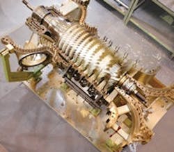
Figure 1. Units such as this can handle large flows with relatively small head. Source: Siemens.

An axial compressor (Figure 1) offers higher efficiency, speed capability and capacity for a given size than a centrifugal compressor. However, it has a narrower recommended application range (Figure 2) and delicate components. Some compressors contain both axial and centrifugal stages (Figure 3).Some operating companies will use whenever possible rugged, versatile and reliable centrifugal compressors instead of dedicated, efficient but fragile axial machines. Large horizontally split centrifugal compressors now are available in capacities up to ≈450,000 m3/h or even more. However, for very large capacities (say, >1,000,000 m3/h), an axial compressor may be the only option.It's difficult to give a general rule for selecting between a very large, sturdy centrifugal compressor and a compact, relatively more efficient, properly optimized more-economical axial machine.DESIGN ISSUESMany chemical plants require axial compressors to operate within a relatively wide operating envelope (capacity/pressure range), and sometimes relatively far from nominal conditions. Considering the steep nature of an axial compressor's curve, this is a great challenge. Variable-speed and the variable inlet-guide-vanes (IGV) systems can provide additional flexibility in operation. A number of issues, including structural, vibration, weight, cost, manufacturability, accessibility and reliability, need evaluation for any axial compressor.
APPROXIMATE APPLICATION REGIONS

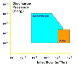
Figure 2. Axial compressors have a narrower operating range than centrifugal machines.

The operating Mach number usually is less than 0.8 for a subsonic cascade but can go up to 2 or more at the tip of a transonic blade assembly. Some subsonic axial stages can develop pressure ratios on the order of 1.5–1.8. The transonic stages operate with pressure ratios of ≈2 and greater while maintaining an acceptable efficiency and aerodynamic design. A well-designed subsonic axial stage can achieve a polytropic efficiency of ≈0.9. The polytropic efficiency for transonic blades is a bit lower, say, ≈0.82–0.89. High peripheral-mean-stage rotor velocities can reach ≈300–340 m/s for subsonic rotors and up to ≈580 m/s for transonic ones. Designers set the annulus radius (or hub-to-tip) ratio, Rhub/Rtip, after a careful optimization that considers aerodynamic, technical, mechanical and economic constraints. For inlet stages, assigned Rhub/Rtip values usually range between 0.45 and 0.65 while outlet stages often get a higher value, typically from 0.75 to 0.9, to achieve a relatively high Mach number. A proper axial compressor design should avoid a flow separation inside the machine. Analysis of axial Mach number distribution along the different blade stages is essential. This distribution should follow an acceptable pattern; variation shouldn't exceed a specified level. The ultimate goal of an axial compressor design is to create an axial blade arrangement with the maximum pressure rise and the minimum total pressure loss, i.e., a relatively high efficiency, along with an acceptable operating range.The different blade and component profiles play an important role because these can affect the nature of the boundary layers and, therefore, the amount of losses (and the operating margins). The stage arrangement is critical; the stage stacking procedure intrinsically is iterative.Maximizing the adiabatic efficiency can significantly impact the choice of stage geometrical and functional variables. In addition, it's important to optimize the surge/stall margins.
DIFFERENT TYPES OF STAGES

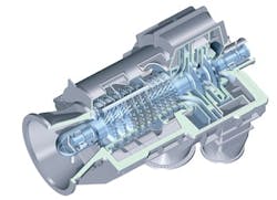
Figure 3. The initial (high flow) stages of this compressor are axial while the final two stages (low flow) are centrifugal. Source: Siemens.

An optimum axial compressor design combines minimum weight with compactness. This calls for decreasing the number of stages and increasing individual stage loading, which can affect the choice of blade shape and cascade parameters.The availability of advanced materials for blade/component construction and high-quality production methods makes it possible to reach levels of aerodynamic loading never before possible in axial compressors while preserving high levels of efficiency for normal and alternative operation cases. This is true both for high-speed subsonic and ultra-high-speed transonic blades. SURGE CONTROLA surge event can damage or even separate the fragile blades of an axial compressor. However, the machine's surge line maps are complex. The surge line could change with a slightly different gas condition or composition. So, an axial compressor requires a dedicated anti-surge system. This usually includes five protection arrangements:• an anti-surge valve;• a hot-gas-bypass valve; • an inter-stage bleed valve (IBV);• an IGV system; and• speed variation. The speed reduction and IGV characterization should be used to map the "surge area" in a two-dimensional plot. In addition to an anti-surge valve, an axial compressor most often is protected by a hot-gas-bypass (HGBP) recycle loop, usually with a hot-gas-bypass valve. This is mandatory if the anti-surge valve isn't installed immediately after the compressor discharge. The IBV also should be opened to provide sufficient flow to the compressor suction to avoid surge at initial stage(s).Dynamic simulation is crucial. The model requires accurate, actual dynamic performance data such as the IGV stroke speed, the control and actuator delay, and the valve stroke time. These data play important roles in dynamic simulation results, anti-surge system design, reliability and overall safety. Proper validation of the model is essential, considering the criticality of avoiding surge and the disastrous consequences of a surge event.The IGV stroke time usually is in the range of 2–6 s. Conceptually, fast response of the IGV system might seem desirable as it could help unload the compressor quickly. However, the IGV stroke could affect the performance curve — for example, the distance between the operating point and surge. Results from some dynamic simulations indicate that fast closing of the IGV mechanism sometimes (depending upon the compressor's operating map) could drive the machine toward surge. This suggests that a moderate IGV stroke time, say, 3–5 s, rather than the fastest time, might be better for surge prevention. The stroke time of an IBV possibly could be as short as 1.5–2 s. However, for a machine in which surge could initiate at the final stages, fast IBV opening could pose problems because it can significantly reduce the gas flow at the final stages. So, it's important to determine an optimum window for the opening time to avoid surge in either section of axial stages. Accurate dynamic simulations are essential for identifying all these optimum values.

AMIN ALMASI is a rotating equipment consultant based in Brisbane, Australia. E-mail him at [email protected].

About the Author

Amin Almasi | rotating equipment consultant

AMIN ALMASI is a mechanical consultant based in Sydney, Australia. He specializes in mechanical equipment and offers his insight on a variety of topics including pumps, condition monitoring, reliability, as well as powder and fluid handling and water treatment.

Sponsored Recommendations

Connect with an Expert!

Our measurement instrumentation experts are available for real-time conversations.

Maximize Green Hydrogen Production with Advanced Instrumentation

Discover the secrets to achieving maximum production output, ensuring safety, and optimizing profitability through advanced PEM electrolysis.

5 Ways to Improve Green Hydrogen Production Using Measurement Technologies

Watch our video to learn how measurement solutions can help solve green hydrogen production challenges today!

How to Solve Green Hydrogen Challenges with Measurement Technologies

Learn How Emerson's Measurement Technologies Tackle Renewable Hydrogen Challenges with Michael Machuca.