Get Relief From Valve Popping

THIS MONTH’S PUZZLER
We’re suffering an annoying thermal expansion problem in the ethylene oxide (EO) lines that feed our reactors: pressure relief valves (PRVs) often pop from solar heating, because lines are blocked in, typically for up to ten minutes. (Our design standard assumes horizontal pipe and a maximum ambient temperature of 95°F, which doesn’t occur very often at our Chicago site: solar flux is 38.7 Btu/h-ft2 for the summer solstice.) The PRVs wouldn’t be such a problem but EO can polymerize and cause them to stick open, which is why the covered area under the reactors is Class 1, Division 1, Group B. The EO feed pipe runs at 55 psig at 60°F. The PRVs are set at 145 psig. Barometric pressure is 14.408 psia. The properties of EO at operating conditions are: density, 66.8 lb/ft3; viscosity, 0.302 cP; heat capacity, 0.476 BTU/lb-F; thermal conductivity, 0.0949 BTU/h-ft2-°R; volumetric thermal expansion coefficient, 0.001°F-1; and bulk modulus, 180,000 psi/ft3.
Our plant engineer is convinced that two inches of calcium silicate insulation in a stainless steel jacket over our 1½-in. Schedule-80 Type-316 stainless-steel pipe largely will eliminate our PRV reliability problem. What do you think?
LOOK AT THE MAKE-UP PUMP
For radial heat transfer conduction to/from a pipe, consider using the following equation: Q = 2πkL(T2-T1)/ln(r2/r1), where Q is heat transfer rate = heat flux × outside surface area of the pipe; k is thermal conductivity; L is length of the pipe; T2-T1 is the temperature difference between air and EO; r2 is pipe radius with insulation; and r1 is the radius without insulation. Consider foam glass insulation (k = ~0.3 BTU-in./hr-ft2 at the temperatures shown in the problem statement). Since EO under blocked-in conditions tends to polymerize, consider a rupture disc (with a pressure indicator) upstream of the relief valve. The problem statement indicates that (if the RV is set properly), for a temperature rise of 35°F (60°F to 95°F), pressure increase of the blocked section is 90 psig (55 psig to the RV set pressure of 145 psig). You can check by a process simulation (or maybe by an ideal gas approximation). In the field, verify the actual set point of the RV in question. The relief valve may be set too low. Alternatively, check the plant operations HMI (screens) to see if there were pressure fluctuations that led to lifting of the RVs.
GC Shah, senior advisor
Mustang Engineering, Houston
TACKLE TWO ISSSUES
There are two problems: polymerization of EO and thermal expansion of EO. Liquid EO polymerization is catalyzed, at ambient temperature, by acids, bases or, in the presence of aluminum, iron or metal oxides. So, all equipment handling liquid EO must be thoroughly cleaned. The thermal polymerization starts around 100°C (212°F). The polymerization reaction is exothermic and self-accelerating, with an explosive decomposition of vapors. With the given site and process conditions, the increase in temperature of fluid is calculated by a simple radiation heat transfer equation: Qradiation/A = hr×(Ts-Ta) + ε×∆R, where Qradiation is in W; A is in m2; hr = ε×σ×(Ts4-Ta4)/(T>sub>s-Ta); ε, emissivity, is 0.6; σ the Stefan-Boltzmann constant, is 5.68×10⁶ W/(m2-K4); ∆R, radiation wavelength difference, is 63 W/m2; and Ta and Ts are the ambient and surface temperatures in K.
Based on this equation, the maximum surface temperature will be 130°F; the credit of fluid at lower temperature, i.e., 60°F, is not considered. In blocked condition, the fluid will attain the same temperature and self-polymerization may start at a slower rate. The exothermic polymerization reaction will further increase the temperature of blocked fluid and self-accelerating will start. As fluid is highly sensitive to increase in temperature, it is advisable to provide thermal insulation. You can consider fiberglass pipe insulation in place of costly calcium silicate insulation. The required fiberglass insulation thickness only will be 25 mm or 1 in.
Along with increase in temperature, the fluid volume also will increase. The coefficient of thermal expansion of EO at 20°C is 1.64×10⁻³ per °C. The relief valve will pop. To avoid this problem, consider a compensator at each end of the pipeline. Refer to “Save Pipe from Bursting with a Compensator,” by David Clucas and Jack Boteler, Chemical Engineering, Dec. 1999. [Ed.: See next response.]
Prakunj Trivedi, senior manager
Uhde India Private Ltd., Mumbai, India
GO WITH FLOW ORIFICES
Given that the minimum ignition energy for EO is only 0.06 millijoules (mJ), it’s easy to see a reason for concern; hydrogen is 0.02 mJ. I solved this puzzle with Excel by defining the allowable temperature rise for the liquid in the pipe, then the heat balance.
My approach involves two “goal seek” iterations. The first solves the temperature rise based on the allowable pressure rise from a mechanical balance on the pipe — the temperature rise is a function of ∆P, i.e., the difference between the PSV set point and the operating pressure: 145-55 psig or 90 psig. The second is a heat balance at the surface of the bare pipe or insulation jacket using the ∆T found.
The mechanical balance equation for the first step is:
∆P = [4E(αL-αp)×∆T(t/Di)×{1/(1-ϒ)}]/[1+(4/3)(E×KT)(t/Di)×{1/(1-ϒ)}]
where E is the Young’s modulus, or tensile modulus, in psi; αL is the linear, thermal expansion coefficient of EO in °F-1; αp is the linear, thermal expansion coefficient of pipe, in °F-1; ∆T is change related to ∆P, in °F; t is pipe wall thickness, in units compatible with Di (the pipe ID); ϒ is the Poisson’s modulus for the pipe wall, which usually is close to 0.34; and KT is the isothermal compressibility, or 1/bulk modulus.
This equation is derived from a mechanical balance around the pipe wall. Although the pipe and fittings are capable of a much greater pressure, the PSVs are not — they are fixed at 145 psig.
A rough energy balance is: solar heat = heat reflection + heat convection from air + heat conduction. I developed equations based on those in the literature for determining these.
When the energy balance was satisfied, I estimated the heat-up time using an equation I adapted from “Unsteady-state Heat Losses from Storage Tanks,” J. D. Paciotti, Chemical Engineering, June 20, 1980. For EO, I calculated an allowable ∆T of only 0.6°F for 1.5 minutes with insulation and 1.1 minutes for bare pipe. For comparison, I ran toluene and water: 2.4 minutes for toluene with insulation and 1.7 minutes without insulation; 6.1 minutes for water with insulation and 7.7 minutes without insulation (water has a high k). Toluene has an allowable temperature rise of 1°F; for water, it’s 1.7°F. Obviously, insulation has little effect on the thermal expansion problem. Perhaps, raising the set point of the relief valves would be of more value. Increasing the allowable pressure rise from 90 psig to 400 provides 7.4 minutes with insulation. A better alternative would be flow orifices with the PSVs as backups in case the orifices become plugged. The PSVs should go to a flare or weak H2SO4 scrubber if possible. An expensive option would be a chilled water jacket for the line; a better choice would be to shade the entire line. Running a similar calculation showed 3.1 minutes for EO with a 90-psi rise without insulation. At 400 psi, a bare shaded EO line would not relieve for 14.7 minutes. This would be the way to go. I would add proper ventilation where flanges or other sources of leaks are located under the canopy.
The solar flux could be eliminated entirely for most of the system by burying the line because ground temperature varies much less than ambient; a double-pipe with EO detection would be required.
Another consideration is the design conditions: “horizontal pipe on summer solstice at 95°F.” This is very conservative. If we considered the vertical pipe, with its lower radiation absorption, or average summer temperatures at the solstice, the heat-up time would be greater. If I assume 80°F, the summer average for June in Chicago, heat-up takes 2.3 minutes for 2 inches of calcium silicate insulation. For the fall equinox, with an average temperature of 76°F, where solar radiation is only 81% of the summer solstice, I calculated a heat-up time of 2.8 minutes. Obviously, though conservative, the design conditions point in the right direction.
Dirk Willard, consultant
Wooster, Ohio
DECEMBER’S PUZZLER
We have a troublesome dilute-phase pneumatic conveying system for the cylindrical soap pellets we make (Figure 1). It uses an airflow of 6,000 lb/h to move 30,000 lb/h of pellets to whichever one of four cyclones we choose. The duct from the bin to the inlet of the blower runs the equivalent of 840 ft horizontally and 290 ft vertically. The system was designed for a total pressure drop to the blower inlet of 78.2 IWC; blower volumetric efficiency is 60%. Every few weeks, our feed screw conveyor clogs and no pellets go into the system. The problem is worst during thunderstorms and least troublesome in the winter, although when the temperature drops our blowers can’t keep up. In addition, we often see salting (dropping out) of pellets when the level in the bin is lowest. Other symptoms are blinding in the dust collector and bridging in the cyclone rotary valves. Our operators think we should increase the airflow, which will require a larger motor. The plant electrical engineer says no because there isn’t a larger bucket in the motor control center. What do you think we should do to improve the system reliability?
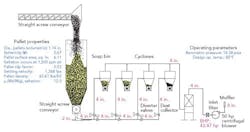
Figure 1. Problems with the feed screw conveyor and from dropping out of pellets afflict system.