This Month’s Puzzler
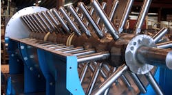
We’re in the dead of summer — the ambient temperature is already 95°F at 90% relative humidity — and our cooling tower ( see figure) can’t cope. We must run at 50% capacity because we can’t keep the batch temperature in range; we’ve offset the process to make product when the ambient temperature is down, such as at night. The condenser on the ammonia refrigeration runs at far above normal temperature, raising the upper system pressure to near the equipment limit of 400 psig. Last week, we blew the relief on the raw materials cooler; on inspection, I saw that the seals on the delivery pump of a cooled product were blown, adding to our troubles. This inspired me to review the entire cooling tower system.
Here’s what I discovered: 1) when we pulled the heads off the ammonia condenser, we found it full of assorted muck including tree seedlings and mud; 2) two office chillers replaced early this year never were inspected before they were removed; 3) we pulled the head on one of the distillation column condensers — the smallest one, at the end of the train — and found no fouling; relief valves have popped on the product cooler because of high vapor pressure.
The maintenance engineer strongly believes that one fouled head is no problem. Production wants inspections of the heads of all the exchangers as part of every outage. The project engineer thinks we should add cooling towers but install them to serve the ammonia system exclusively, allowing the reactors and condenser to consume most of the cooling water. Another engineer suggested inspecting more condenser heads and, if needed, installing a filtration system at the discharge of the cooling tower pumps. The instrument engineer recommends automating the cooling tower to increase the cooling and system pressure, thereby improving cooling throughout the system.
Do you think we’re in trouble? What’s the best bang for our buck?
Check Many Factors
Consider the following:
1. First, use a psychrometric chart to determine the theoretical minimum temperature (wet bulb) you can get with the cooling tower at your location. In practice, though, the minimum you can achieve is 4–5°F above the wet bulb temperature. (This is called approach.) Because you have high relative humidity of 90% at ambient of 95°F, psychrometric charts show wet bulb close to 95°F. Compare the temperature of cooling water coming out of the cooling tower with the wet bulb temperature. If this temperature is close, your cooling tower is functioning the best it can. However, if the temperature is much higher (say, approach is 10–15°F), you can improve the operation of the cooling tower.
The key to good performance is effective contact between the water flowing down the cooling tower and air. Factors that can impair this contact are water flow distribution as well as air flow rate and distribution. Check cooling range and compare it with the design value. If the cooling range is much smaller than design, your tower is not working properly. So:
• Inspect the water distributing nozzles at the top of the tower. They can get muddied up if water has high suspended solids. You can rod them out.
• Ensure louvers are not blocking air flow.
• The figure shows mist eliminators. These typically are tightly packed. They could get plugged, resulting in air-flow maldistribution. They are difficult to clean on-line.
• Check the cooling water fans, their rotation, and vibration. They should run smoothly. Measure their amp-draw to get an idea about air flow.
The above items do not require shutdown of the cooling tower.
• Examine the splash bars, i.e., the slats, which serve to help improve air-water contact. If a large number are missing, you would need to shut down the tower and install new splash bars.
• If the towers contain fill (fill in good working condition can achieve much better air-water contact than slats), look for plugging by suspended solids. On-line cleaning of fill plugging will require lowering the cooling tower pH and increasing blowdown. This is a slow process. Before you do this, carefully review the impact of low pH and increased blowdown on plant equipment and the blowdown treatment facility. If you are using cooling-tower-treatment chemicals from a vendor, seek its help in planning this cleanup.
2. Check solids (suspended and dissolved). As a general rule, a dissolved solids level above, say, 5,000 ppm is considered high and can accelerate scaling and fouling. Get an analysis of dissolved and suspended solids. Consider installing a side-stream filter (or, additionally, softener such as zeolite) depending on the chemicals you find in the analysis. Scaling chemicals such as CaCO3 become problematic above, say, 700 ppm or so.
3. Check cycles of concentration (COC), i.e., the ratio of dissolved solids in the circulating water to those in makeup water. Higher COC is good for minimizing water waste but tends to enhance scaling and fouling. A COC that is too high, say, above 4, will see a substantial increase in scaling and fouling. If you are operating at high COC, consider lowering it by increasing the blowdown.
4. The quality of makeup water also can affect the COC you can live with. Ensure makeup water does not have excessive solids.
5. Now, to deal with heat exchanger fouling, consider in the short term localized additions of dispersants at the water inlet of the heat exchanger. In general, dispersant addition is a part of the overall treatment program. If the tower is heavily fouled, a short shutdown to clean up the entire system is desirable. However, this apparently is not a good option for you; so, instead, consider increasing blowdown and side-stream filters.
The on-line approaches discussed above are slow — improvements will be gradual. As you do these, monitor water quality.
6. You can check if the cooling tower has enough capacity to handle the heat load from your plant: estimate total BTU/h load from all heat exchangers and compare that with the cooling tower capacity. Refer to design data sheets. It is unlikely the tower was undersized initially; however, later additions of coolers may have led to exceeding the cooling capacity.
7. Some long-term options to think about include: side-stream filters; conductivity meters and auto-blowdown; filters and softeners on the incoming makeup water if its quality is not up to par; automatic addition of treatment chemicals including biocides, dispersants, corrosion inhibitors and other chemicals; monitoring the U-values of heat exchangers on-line; and regulating cooling water flows to avoid velocities below 3 ft/s to minimize fouling. Typically, 6–7 ft/s tends to help with heat transfer and minimize fouling.
GC Shah, consultant
Houston
Be Systematic
You must start by determining the flow rate required for each cooler using cooling water. First, survey what flow meters you already have in place. If you don’t have flow meters everywhere, using portable ultrasonic flow meters may be a good option. These devices have come far in the past 30 years; they will diagnose the flow characteristics — turbulent, laminar, gassy or a slurry. Unfortunately, they do need a good deal of straight pipe, about 10 pipe diameters upstream and 5 diameters downstream — but that depends on other obstructions like valves and bends.
Next, collect all the data sheets for the coolers and material balances, if available. Don’t rely on the data sheets to tell you what the flow should be in a particular cooling leg; heat exchangers generally are oversized. Also, don’t rely on inputs from design engineers because they may not be experts on the process; get your own data.
Now, you’re ready to compare the survey data against the data sheets and material balance. Look hard at any discrepancies between the data sheets and the material balance and the measurements taken for the coolers. The measured flow rates should be less than the rates on the data sheets or from the balances; if not, the cooler is too small. Usually, a cooler is designed for perhaps 130% of required flow rate. The first pass probably won’t tell you much; you’re after a baseline!
Obviously, you’ll want to do the first survey when the coolers are free of debris. If not, the data are still useful but will have to be compared to future measurements. The next time you do a survey, use the results to determine if a cooler is fouled.
Some might suggest measuring the pressure drop across the coolers instead. However, this only works if you’ve got the proper tees set up and ready to go and have a precision gauge you trust. Don’t ever leave the gauge in the field; it will become unreliable after a few months. Here’s the key thing to know: you must use the same gauge for upstream and downstream measurements across a cooler — the variation in accuracy between two gauges probably will ruin your ΔT calculation. You will find that repeatedly screwing in gauges is more trouble than using an ultrasonic flow meter. Plus, you may not see much difference in pressure drop between a fouled heat exchanger and a clean one.
Filtration is a good idea if you’ve got the money. You will have to separate continually and blowdown the solids from the filter back into a sump with a screen on top. The screen will foul unless you skim it; fortunately, continuous skimmers are available.
Automating the towers makes absolute sense. I cut our plant electrical bill by 10% by doing just that.
Something else you should be thinking about is global warming. (See: "Consider the Effects of Global Warming.”) Most cooling towers are designed for about 80°F wet bulb. Much of the United States will be well above that during future summers. If you’re popping relief valves now, imagine what risk you’ll be running at 95°F wet bulb temperature! You may want to opt for better refrigeration for key processes in your plant.
Do the study first! Then, consider the economics. The cost of an ammonia release is perhaps $5,000/each depending on the severity and maybe $200,000/d in downtime. So, any project under $2 million probably is worth consideration.
Dirk Willard, consultant
Wooster, Ohio
December’s Puzzler
I’m fresh out of college and have been handed a project for which I need help. I’m installing a centrifuge for concentrating a pharmaceutical product from a reactor’s mother liquor. This is an expansion plant, designed by corporate engineering, for handling a new process.
The mother liquor is fairly sticky. I only have two data points: 31 cP at 108°F and 72 cP at 72°F. With the product, in a concentration of 13% by mass, the viscosity is 52 cP, and 101 cP, respectively. I am told the product starts to degrade above 115°F.
The density ratio between the product and the liquor is 1.3:1 for the batch stack centrifuge. I read that upstream factors could affect this ratio.
I still haven’t figured out how I’m going to do the cleaning-in-place, given the sensitivity of the product to low pH and high pH. I’m worried about residual materials.
My problem primarily is instrumentation because we are under orders to reduce the labor costs per batch. I’m kind of on my own here. I have some ideas on what controls are critical versus just nice to have. What do you suggest as far as instrumentation?
Send us your comments, suggestions or solutions for this question by November 12, 2021. We’ll include as many of them as possible in the December 2021 issue and all on ChemicalProcessing.com. Send visuals — a sketch is fine. E-mail us at [email protected] or mail to Process Puzzler, Chemical Processing, 1501 E. Woodfield Rd., Suite 400N, Schaumburg, IL 60173. Fax: (630) 467-1120. Please include your name, title, location and company affiliation in the response.
And, of course, if you have a process problem you’d like to pose to our readers, send it along and we’ll be pleased to consider it for publication.

