Centrifugal pumps at chemical plants and refineries usually rely on mechanical seals to prevent fluid from escaping. Every seal connection is a potential leak point — and any leak can lead to asset damage, unplanned downtime, environmental issues and safety risks. Therefore, taking a holistic view and paying special attention to not only the mechanical seal itself but also the entire seal support system is important.
Mechanical seals became the dominant sealing system for petrochemical processing operations in the 1980s, prompting the American Petroleum Institute (API) to establish a committee to write standards for these components. The committee’s work led to the publication of a standard, “API 682 — Shaft Sealing Systems for Centrifugal and Rotary Pumps,” in 1994 [1]. Its mission statement read: “This standard is designed to default to the equipment types most commonly supplied that have a high probability of meeting the objective of at least three years of uninterrupted service while complying with emissions regulations.”
Now in its fourth edition [2], much of the API 682 standard focuses on mechanical seals. However, it also devotes significant space to seal support systems and their proper operation due to their critical importance in the overall reliability of the entire pump skid. Best practices covered in the standard include proper seal support system design, elimination of potential leak points wherever possible, and selection of components that simplify maintenance. This article will explore these best practices to help plants increase reliability, maximize efficiency and improve safety.
More Leak Points, More Risk
Most plants historically have handled fluid conveyance with piping, which typically is made from carbon steel and features numerous threaded connection points throughout each run. So, sites often also turned to piping for seal support systems. However, the current edition of API 682 recommends reducing threading and connection points wherever possible. This guideline has fostered a notable shift to bendable tubing systems becoming the preferred choice among seal manufacturers, end-users, and pump original equipment manufacturers. Plants also have the option to weld carbon steel pipe to minimize threaded connections but the corrosion resistance, flexibility and efficiency benefits of using stainless steel tubing often tip the scales in its favor.
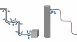
Figure 1. Opting for tubing instead of threaded piping can reduce the number of connection points significantly and, thus, the potential for leaks.
By design, tubing can reduce the number of connections to just those at the mechanical seal and the seal support system (Figure 1). Therefore, the system might only have two to four potential leak points, depending on its configuration. Minimizing the number of connection points and reducing leak potential are possible due to a variety of factors, including:
• Innovative connections, such as flange adapters and extended male connectors; these help decrease the number of connections from threaded ports on seals and seal pots by eliminating the need for multiple fittings.
• Leak-tight tube fittings that can prevent leaks during regular system operation and are easier to service when needed.
• Tubing made from annealed stainless steel, so it can be bent, which lessens the need for fittings and connections. It also resists corrosion, which reduces ongoing maintenance.
The use of tubing provides further financial benefit when examining the maintenance, repair and operation (MRO) costs of the pump, seal and support system. During maintenance operations that require reworking welded piping around pumps, using tubing instead can eliminate the need for costly on-site welding and also speed installation time to reduce downtime.
While bendable tubing offers efficiency benefits to cut installation and MRO labor costs, it is more expensive than carbon steel piping; it can become particularly expensive when using special alloys to combat corrosion. Construction of piping systems in special alloys also is possible but material options are more limited. Therefore, system designers may need to weigh the overall costs of using either tubing or piping — while also factoring in corrosion resistance, aesthetics, MRO activities, supply logistics and more — to make a decision.
Carbon steel piping is perfectly acceptable for many seal support systems such as flush plans. However, it can pose a risk for applications in which moisture is present and internal corrosion is a possibility. For example, the scale that commonly builds up on the inside of carbon steel pipe can break away, flow downstream and then lodge in the gap between seal faces or clog an orifice. Using carbon steel in systems where scaling is a possibility calls for scheduled preventive maintenance (PM) and close monitoring of the system.
Figure 2. Installing the plan onto a panel enables proper identification of components and processes and also streamlines system operation.
Ultimately, the choice between pipe and tubing might come down to the comfort level of the person making the decision. That said, optimizing the system and making it more reliable necessarily should place priorities on decreasing maintenance, improving performance, and enhancing safety by reducing leak points and threaded connections wherever possible.
System Optimization
The reduction of leak points is just one aspect of optimizing the system. There also are best practices to follow during the initial design of the mechanical seal and seal support system to help operators ensure proper operation of the seal and pump as well as to improve safety and reliability.
1. Make inspection easier for operators. During turnarounds and other operations such as routine maintenance, pumps and seal support systems often are visually inspected. Simplified designs can facilitate proper commissioning and operation of seal support systems, lowering the risk of operators making common mistakes.
Creating even small obstacles for operators increases the risk of missing trouble signals and, thus, reducing reliability. For example, API 682, 4th ed., shows a Plan 32 design for a flush stream from an external source as multiple instruments and components installed together in a run using either piping or tubing. While functionally correct, this design provides the operator with little information regarding the operation of the system, what information is important, and why it is important. The location of the system can pose further difficulties; if placed next to the seal on a pump, the operator must bend down to read instrument information.
An alternative and more-effective solution is to arrange these components on a panel using the Plan 32 design as a template (Figure 2). Mounting the components to a panel increases awareness that the configuration is a distinct system, which helps operators better identify components and their functions as well as confirm proper operation. A few best practices to follow include:
• Place all instruments at eye level rather than locating components on a less-accessible piping or tubing run.
• Meet API 682, 4th ed., design recommendations (in 9.1.5) that state: “All controls and instruments shall be located and arranged to permit easy visibility by the operators, as well as accessibility for tests, adjustments, and maintenance.”
• Clearly display part numbering information, flow path indication and operator instructions to ensure safe and reliable startup and shutdown of pumps and seal support systems.
Figure 3. Using high-quality, easy-to-maintain components can maximize uptime of systems such as this API Plan 22 cooled flush system with strainer.
2. Simplify maintenance. Like the equipment they support, seal support systems typically operate continuously — so, their reliability is crucial. Using high-quality materials (Figure 3) and ensuring the systems are well maintained are important to prevent leaks and costly downtime.
Seal support systems contain commonly serviced items, such as strainers, flow meters and other instruments. Placing components in inconvenient locations can hinder their getting proper attention and adequate PM, especially if a plant is understaffed. Design should ensure operators can simply and safely perform PM on these systems. A well-designed and dependable system can help a plant reduce maintenance needs and costs.
Consider the process for performing general pump maintenance, which requires blocking in and draining the pump and support system. A well-designed support system can simplify this maintenance requirement by including low-point drains that allow purging of fluids quickly and safely. High-point vents also are important to include for removal of any entrapped air. Providing installers with the proper tubing and components, along with a drawing showing where to place vents and drains, ensures correct system installation and easy performance of future maintenance.
API 682, 4th ed., also recommends using block-and-bleed configurations for all gauges (Figure 4), so technicians can swap out a broken gauge with ease. If systems don’t include this feature, as gauges fail, operators likely will lack critical information until the pump and support system can be decommissioned to replace the gauge.
For seal pots, API 682, 4th ed., encourages easy accessibility. It (in 8.1.8) stipulates: “Local operation, venting, filling, and draining shall be accomplished from grade. Unless otherwise specified, systems that require the use of a ladder or step or that require climbing on the baseplate or piping are not acceptable.” Many plants have older seal pots with just a pipe plug at the top. Having operators climb a ladder to top off the pot can expose them to process vapors and generally is an unsafe practice; so, avoid this altogether.
Lastly, a wide variety of tubing connections and design options exist that allow easy removal and replacement of every serviceable component in a seal support system while continuing to operate the system. Implement these technologies wherever possible to help simplify and streamline seal support system maintenance and operation.
Improve Safety And Reliability
Mechanical seals are only as good as the systems that support them. Careful design and use of high-quality materials for seal support systems can significantly enhance the operational efficiency, reliability and safety of a plant. Implementing design best practices can help reduce costs and reduce headaches.
Figure 4. Using a block-and-bleed configuration enables easy gauge replacement without the need to decommission the pump and support systems.
To recap the actions plants can take to realize better results with their seal support systems:
• Consider using tubing instead of threaded or welded pipe to decrease installation and maintenance costs.
• Reduce potential leak points and eliminate the use of threaded connections wherever possible.
• Make the design intuitive to lessen operator error.
• Mount systems on panels with proper labeling for easy maintenance and to promote system reliability.
Finally, always follow API 682, 4th ed., best practices to avoid seal failures and the associated costs of replacement and downtime, while also creating a safer and more reliable operation.
SEAN HUNSICKER is market manager, chemical & refining market for Swagelok Co., Solon, Ohio. Email him at [email protected].
REFERENCES
1. “API Standard 682 — Shaft Sealing Systems for Centrifugal and Rotary Pumps,” 1st ed., American Petroleum Inst., Washington, D.C. (1994).
2. “API Standard 682 — Shaft Sealing Systems for Centrifugal and Rotary Pumps,” 4th ed., American Petroleum Inst., Washington, D.C. (2014).


