This Month’s Puzzler
We manufacture formaldehyde using DuPont’s Formox process in a 30-yr-old system. Methanol is oxidized over a molybdenum-iron oxide catalyst at 600°F in a fixed-bed reactor: CH3 + ½O2 → CH2O + H2O. We replaced the catalyst several months ago — we had stretched the service life of the old catalyst to 18 months from the usual year because of the pandemic.
We recently suffered a tube failure in the cooling water (boiler feedwater) surrounding the reactor. The downtime finally allowed us to inspect the reactor. We’d wondered for three months why methanol conversion dropped from 88% with fresh catalyst to a paltry 79%; the methanol registered downstream had crept up slowly. (We had ignored this because the old catalyst gave 83% conversion.) In addition, we saw more paraformaldehyde fouling of downstream equipment as we raised the reactor temperature to 690°F from 620°F. We also increased the oxygen content to the reactor by 25% to push the reaction. The effect was negligible in improving conversion. However, we noticed an increase in trace formaldehyde in the absorber downstream.
We run our boilers at 400 psig. The recovered steam produced by the reactor feeds into the main feedwater tank. Some engineers at corporate call it “dirty steam” and worry the boilers are being fouled. One suggestion was to sample the feedwater tank and discuss additional chemical treatments to prevent a plantwide problem with steam.
What do you think caused the cooling water leak? Is there really a problem with the boiler feedwater? Did our attempt to raise conversion lead to any lasting damage? Is there a way to identify this problem before it prompts major problems?
Focus On A Few Possible Culprits
In a broad sense, tube failure could stem from one or combination of the following:
1. Vibration caused by vortex formation due to boiler feedwater flow around the reactor tubes — or fatigue (from exceeding the useful life of the tubes);
2. Vibration from water hammer caused by flow of steam (formed by heat transfer of reaction heat to feedwater) and boiler feedwater; and
3. Poor water chemistry resulting in inadequate removal of dissolved oxygen, CO2 or hardness, and lack of pH control.
Without information about the material of construction of reactor tubes and pressure on the boiler feedwater side (at the reactor tubes), I only can offer some general observations:
Visual and metallographic examination of leaking tubes and leak locations will help identify the root cause of the leak or leaks. However, finding the culprit — especially in complex situations — may require considerable sleuthing and possibly inputs from vibration and metallurgy experts. For many situations, though, visual clues are immensely helpful.
Visually, you generally will not see loss of metal with leaks caused by vibration or water hammer. If boiler feedwater (BFW) pressure at the reactor tubes is less than the saturation pressure of steam, steam could form at the reactor and could cause water hammer. On the other hand, if there is a back-pressure control with set pressure sufficiently high, then steam will form downstream of back-pressure control (in the BFW tank) and there is less chance water hammer will take place at the reactor tubes. For flow-induced vibration, if the vortex-causing frequency coincides with the natural frequency of the tubes, then vibration will intensify.
Typically, dissolved oxygen will prompt pitting corrosion — which is visible by indentations on reactor tubes. On the other hand, CO2 causes groove corrosion and thinning of reactor tubes (loss of metal). Low pH also will entail metal loss due to acidic corrosion. High pH, on the other hand, could lead to caustic corrosion. Scale can result in under-deposit corrosion and CO2 corrosion by scale decomposition.
If these are the causes, then the broad strategy is to control water chemistry:
• determine allowable levels of dissolved oxygen at the BFW pressure at the reactor tubes; consider deaeration or oxygen scavenger treatment with hydrazine substitutes;
• control CO2 by amine treatment, scale by zeolite bed operation, and solids by conductivity controlled blowdown; and
• consider placing the BFW tank under a nitrogen blanket. If nitrogen is not available or suitable, use natural gas — of course, you must address the flammability issue.
You quite possibly may determine that a combination of mechanisms caused the tube leaks. You then can develop corrective action.
You also state that conversion dropped from 83% to 79%. This is to be expected because water vapor (leak-caused ingress of water/steam to the catalyst bed) inhibits oxidation of methanol to formaldehyde (H-CHO an aliphatic aldehyde).
GC Shah, senior advisor
Wood, Houston
Don’t Be Hans Brinker
Old equipment often is poorly maintained. Managers don’t see a problem for many years and, so, give up on routine inspections. Then, they become a plant version of Hans Brinker — plugging holes as they spring up, in tubes rather than dikes.
Fouled steam can degrade performance of reboilers throughout your plant. In addition, operating at >300 psig will affect the water quality of the steam condensate recovered. (The allowable impurity of Fe2+ and Cu1+ for boiler feedwater is half of what’s tolerated for <300 psig boilers: 0.05 ppm versus 0.100 ppm for Fe2+ and 0.025 ppm versus 0.05 ppm for Cu1+.) You can add tens of thousands of dollars’ worth of chemicals to counteract the fouling, with side effects. Or you can spend a lot of money buying equipment to trap the foulant before it affects the boiler and plant exchangers; most powerhouses I’ve seen don’t have that kind of space.Dumping the steam might seem tempting but it’s far too valuable to an operation like this. When considering steam condensate recovery, the cutoff for a 4-yr payback (~25% return on revenue) is about 600 lb/h based on a cost of $22/1,000 gal of steam condensate.
Instead of plugging holes in the tubing as they spring up, you can bite the bullet — shutting down for the week it will take to identify the leaks and make a plan to repair them all. Do a thickness reading as part of your inspection, although alloy steels don’t tend to thin from corrosion. If the thickness is reasonable, then cut out a section of the coil for dye penetration testing followed by electron microscopy. The results might prompt you to buy a new vessel — a decision you couldn’t reasonably make before such testing.
Once you’ve repaired the obvious leaks, plan for a longer outage to: replace the vessel and the coil; replace only the coil; or, hopefully, just repair the coil.
You may want to run a fluorescent dye test at low pressure to detect any small holes or check sections of the coil difficult to inspect, like right next to the vessel wall. At low pressure, the dye will accumulate where it escaped. Run this test once, cut out the affected coil and replace; then run it again to identify any holes that were missed the first time. It’s amazing how long you can extend equipment well past its zero depreciation point with vigilant inspections and effective repairs.
One problem you will have to live with for a while: the foulant is all through your plant from the boiler feedwater tank to the individual heat exchangers. It will be decades before that problem is behind you.
Like most, this episode has a positive side. At least, you learned that increasing the O2 rate and raising the temperature had negligible effect on the reactor conversion. In fact, a high temperature might have exceeded limits on the coil. Also, seeing product downstream in the column may be useful in predicting the limits of the distillation tower.
Dirk Willard, consultant
Wooster, Ohio
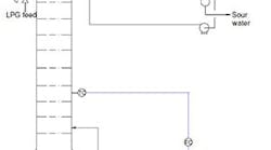
Figure 1. Changes to pressure relief system cause concerns for original designer.
December’s Puzzler
We completed an engineering package for a de-ethanizer system (Figure 1) that is part of an overall expansion of a refinery. This involved replacing some lower trays because of fouling and capacity limitations and repairing corrosion in the feed tray and tubes in the air heat exchanger and water condenser. Construction is done. However, the pressure relief system — I did its initial design a few years ago but that has been significantly modified — troubles me.
I noticed the following changes to my design: 1) a block valve was added in front and back of the water (thermal) expansion relief valve (RV); 2) that valve is upside down and someone left the cap at the discharge; 3) the RVs that were located on the reboiler, condensate knockout drum, condensate tank and water condenser have been removed and capped; 4) the pilot RV has been moved from the top of the vessel to the condensate pipe; 5) an isolation valve has been added to a long inlet pipe and the discharge pipe was extended to a duct leading to the flare stack; and 6) the reboiler RV has been replaced by a restrictive orifice on the steam supply (or so I am told by one of the client’s engineers working on the project). These changes really concern me, not the least because my name is on the calculations if something goes wrong.
My managers are telling me the refinery is happy and, so, not to rock the boat.
What do you think? What should I do? Should I ask for the new calculations for my files?
Send us your comments, suggestions or solutions for this question by November 6, 2020. We’ll include as many of them as possible in the December 2020 issue and all on ChemicalProcessing.com. Send visuals — a sketch is fine. E-mail us at [email protected] or mail to Process Puzzler, Chemical Processing, 1501 E. Woodfield Rd., Suite 400N, Schaumburg, IL 60173. Fax: (630) 467-1120. Please include your name, title, location and company affiliation in the response.
And, of course, if you have a process problem you’d like to pose to our readers, send it along and we’ll be pleased to consider it for publication.


