The previous articles in this series on level control focused on proportional-integral control ("Neglect Level Control at Your Peril" and "Be Levelheaded About Surge-Tank Control") and use of nonlinear control equations ("Avoid Vessel Level Trips"). In this final installment, we'll look at cascade control.
In digital systems, proceeding from a simple feedback to a cascade configuration requires only one hardware component — a device to measure the inner loop variable. In level control schemes, the sensor monitors flow through the final control element. This permits configuring a flow controller and implementing a level-to-flow cascade. The level controller (in the outer or master loop) provides the set point to this flow controller (in the inner or slave loop).
In most cascade applications the objective is to improve control of the outer loop variable. Level control differs in this regard. Especially when used with surge vessels, the aim is to allow level to vary as much as possible "within reason" (meaning that no high or low level trips occur during routine process operations). Rarely can you justify purchase and installation of a flow meter on the basis of improved control of vessel level.
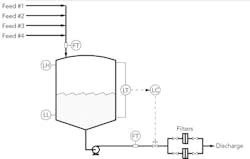
Figure 1. Switching to a clean filter causes disturbance to discharge flow.
Particularly with surge vessels, the level controller intentionally is tuned to respond slowly — with the objective of maintaining as smooth a discharge flow as vessel capacity permits. Any disturbance to the discharge flow will affect vessel level but not very quickly, thus exposing the downstream processing unit to upsets from the altered flow.
FILTER ON DISCHARGE FLOW
In the process shown in Figure 1, the discharge flow goes through one of two cartridge filters, with only one in service at a given time. As fluid passes through, pressure drop across the filter slowly increases. When this pressure drop attains a specified value, the flow is switched to the other filter.
On switching to the clean cartridge, the pressure drop across the filters abruptly decreases. The major consequence is a sharp increase in discharge flow. This affects vessel level but the impact, except for possibly raising the probability of a process trip on low level, is of no concern. What is of concern is the potential repercussion of the higher flow on the downstream unit.
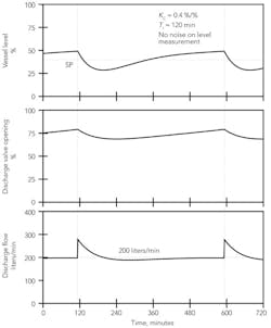
Figure 2. Switching filters increases discharge flow, spurring decrease in level.
Figure 2 illustrates the effect of switching the filters (at an interval of approximately 8 hours) for a constant feed rate of 200 liters/min and no noise on the level measurement. The discharge flow abruptly increases, which causes the level to decrease. The subsequent drop in discharge flow stems partly from the response of the level controller and partly from the increased resistance to flow within the filter. When the level controller is conservatively tuned, equilibrium conditions aren't established prior to the next switch.
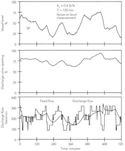
Figure 3 illustrates the effect of switching the filters for a varying feed rate and noise on the level measurement. On each switch of the filters, the discharge flow sharply rises. This is apparent in the trend of the discharge flow but not in the plots of vessel level or level controller output. Variability of the feed to the vessel causes comparable changes in the magnitude of discharge flow during normal operations. However, the change on switching the filters is sudden. For most unit operations, abrupt changes to the feed are major upsets; the same change over a longer time period has fewer consequences.
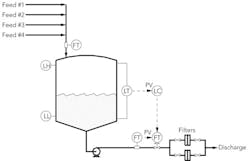
Figure 4 presents the level-to-flow cascade control configuration. The cascade consists of two loops:
1. Inner loop. The flow controller positions the discharge control valve so discharge flow is at or near the set point provided by the level controller.
2. Outer loop. The vessel level controller provides the set point to the discharge flow controller.
Figure 3. Higher discharge flow after switching filters isn't apparent from vessel level.
Applications of cascade require more attention to tuning. When the inner loop is a flow controller, you can use typical flow-controller tuning, such as a controller gain of 0.2 %/% and a reset time of 3 sec. You must begin by verifying these coefficients function properly. When the outer loop is very slow (as is the case for the level controller), tightly tuning the inner loop isn't necessary.
For the level controller, the tuning for the simple feedback scheme was a controller gain of 0.4 %/% and a reset time of 120 min (as detailed in previous parts of the series). Adding the flow controller only nominally affects the dynamics of the process, so a reset time of 120 min remains suitable in the cascade configuration.
However, the controller gain for simple feedback isn't necessarily still appropriate. In the cascade configuration, discharge flow varies linearly with level controller output (which is the discharge flow set point). But in the simple feedback scheme, the relationship between discharge flow and level controller output (the discharge control valve opening) is more complex and rarely quantified. Depending on valve sizing and flow system characteristics, the control valve (and, consequently, the level controller output) frequently operates over about half the full range. For a properly sized equal-percentage valve, the range is 50–100%. For a grossly oversized equal-percentage valve, a range of 0–50% is more likely. Unfortunately, anything is possible. For cascade, a higher controller gain probably is required, but not necessarily one twice as high.
Figure 4. Level controller in outer loop provides set point for flow controller in inner loop.
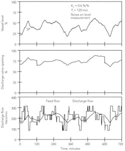
Figure 5 presents the performance of the cascade configuration for a varying feed rate and noise on the level measurement. A controller gain of 0.4 %/% leads to occasional trips on low level, making a gain of 0.6 %/% more appropriate.
On switching the filters, an abrupt decrease occurs in the discharge valve opening. On the time frame of the trend in Figure 5, the response of the flow controller is instantaneous. However, there's no effect on discharge flow. (The decreased valve opening merely compensates for the lower pressure drop across the filters.) In the cascade configuration, the flow controller completely isolates the level controller from any consequences from switching the filters.
Figure 5. Flow controller isolates level controller from any consequences when filters are switched.
CONSTANT TOTAL DISCHARGE FLOW
Up until now we've focused on maintaining as constant a discharge flow as possible given the variations in feed flow to the vessel and the capacity of the vessel to smooth these variations. Some applications, though, add a complication. In them:
• Two (or possibly more) discharge flows are present, with the vessel level controller manipulating one.
• Other factors determine the second discharge flow and that flow isn't constant.
• Any change in the second flow must lead as quickly as possible to an equal but opposite change in the flow regulated by the vessel level controller — that is, the total discharge flow must remain constant.
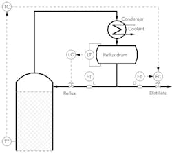
Figure 6. Manipulating distillate flow regulates temperature in upper stage of column.
Distillation provides an example of such a requirement. Figure 6 illustrates the upper section of a column. The overhead vapor is totally condensed. Some of the condensate exits as distillate product; the remaining condensate returns to the column as reflux.
The control configuration consists of a temperature-to-flow cascade. Distillate flow manipulation regulates the temperature on the control stage in the upper section of the column. The temperature loop responds slowly, so providing a controller for distillate flow is advisable. Reflux manipulation regulates vessel level.
Reflux flow can't be zero; the minimum depends on the column internals. In the simple feedback configuration shown in Figure 6, you must convert this minimum flow to a corresponding valve opening and impose a minimum on the opening. The availability of a reflux flow measurement permits implementing a level-to-flow cascade. This enables imposing the minimum reflux flow via a lower limit on the reflux flow set point.
In developing control configurations for distillation, the first priority is to establish how to regulate product compositions. To maintain overhead composition at its desired value, the scheme shown in Figure 6 uses the temperature on a control stage in lieu of an overhead composition measurement. When you must control both overhead and bottoms compositions, interaction between these two loops is a given — anything that affects one composition impacts the other (a consequence of the material balances). Using a steady-state separation model, you can perform an interaction analysis to determine whether to control overhead composition using reflux flow or distillate flow. When the answer is distillate flow, the configuration in Figure 6 is appropriate.
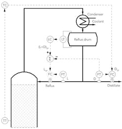
Figure 7. This approach provides faster response than that with a temperature controller.
The steady-state separation model assumes the total material balance around the condenser and reflux drum is enforced at all times, i.e.:
V = L + D
where V is overhead vapor flow, D is distillate flow and L is reflux flow. The reflux drum level controller is responsible for closing this material balance. It will close the material balance over the long term — but not in the short term.
For the control configuration shown in Figure 6, the performance of the temperature controller depends on changes in distillate flow quickly translating into changes in reflux flow, which is the responsibility of the level controller. Suppose the level controller is on manual, giving a constant reflux flow. Then, the only effect of increasing distillate flow is to drain liquid from the reflux drum; changes in distillate flow don't affect overhead composition or the temperature of the control stage in the upper section.
The term "cascade" as normally understood doesn't apply to the relationship between the upper-stage temperature controller and the drum level controller. However, two attributes of cascade configurations do come into play in the control scheme in Figure 6:
1. The temperature controller totally depends on the level controller (changes in distillate flow must be translated to changes in reflux flow).
2. Reflux flow must change rapidly with respect to the dynamics of the temperature loop.
The dynamics of the drum level loop preferably should be about five times faster than those of the temperature controller. How rapidly the level controller can respond depends on the size of the reflux drum and how much noise is present on the drum level measurement.
Another Option
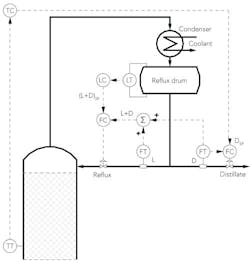
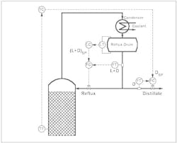
Figure 8. This configuration relies on a computed value of total flow from the reflux drum.
Alternatives to the configuration in Figure 6 deserve consideration. Using two flow measurements (distillate flow and one more), you can provide logic that translates a change in distillate flow into an equal and opposite change in reflux flow. The dynamics will be typical of flow loops and, thus, far faster than those of the temperature loop.
Figure 7 presents one approach. Its key attributes are:
• The output of the drum level controller is considered the target for the total flow leaving the reflux drum.
• The measured value of distillate flow is subtracted from the total to give the set point for reflux flow.
This configuration is a level-to-flow cascade with a computed flow set point. You can impose the minimum reflux flow as a lower set point limit on the reflux flow controller.
Figure 8 illustrates an alternative approach. Its key attributes are:
• The output of the drum level controller is the set point for a flow controller whose process variable (PV) is the computed total flow from the reflux drum.
• The total flow from the reflux drum is computed by summing the measured values for reflux and distillate flows.
The configuration is a simple level-to-flow cascade with a computed value for the flow.
Figure 9 shows yet another approach. Its key attributes are:
• The output of the drum level controller is the set point for a flow controller whose PV is the measured total flow from the reflux drum.
• If a value for reflux flow is required, it must be computed by subtracting distillate flow from the measured total flow from the reflux drum.
The level control configuration is a simple level-to-flow cascade.
Still Another Approach
Figure 9. This control scheme requires a measurement of total flow from the reflux drum.
With the configurations shown in Figures 7–9, we can say the following about the performance of the upper-stage temperature controller:
• The flow controller that drives the control valve on the reflux must be functioning. For the configuration in Figure 7, it must be using the remote set point computed by the summer.
• Level controller tuning doesn't impact the performance of the upper-stage temperature controller.
• Switching the level controller to manual doesn't affect the upper-stage temperature controller.
However, these advantages come at a price — two flow measurements are required. Older towers likely lack the necessary flow meters. Newer installations probably have them, as the trend is to provide flow measurements wherever practical.
A disadvantage of the configurations in Figures 8 and 9 is that you can't impose the minimum reflux flow simply by specifying a lower set-point limit for the flow controller. Adding logic to impose the minimum increases the complexity of these configurations.
In these configurations as well as the simple feedback scheme in Figure 6, problems arise when reflux flow is much smaller than distillate flow (external reflux ratio L/D «1). Regardless of the configuration, you are controlling the level with a minor discharge flow and, thus, making large changes (on a percentage basis) in a small flow. In most cases, the control valve repeatedly will be driven fully open or to the opening corresponding to the minimum reflux flow. Fortunately, composition control analysis rarely recommends the configuration in Figure 6 when reflux flow is small compared to distillate flow.
CECIL L. SMITH is president of Cecil L. Smith, Inc., Houston. E-mail him at [email protected]. This article is based on concepts from his book "Practical Process Control," published by John Wiley & Sons.

