Tube corrosion, fouling and leakage in heat transfer equipment at chemical plants creates unfavorable conditions that can seep across the entire business. Indeed, inefficient heat transfer is a common bottleneck at sites around the world, often adding significant expense to operations.
The bare carbon steel tubing used in heat exchangers, condensers and other heat-transfer equipment is a key culprit. However, applying a polymer coating to the inner diameter (ID) of the tubes can cut plant and equipment downtime, extend intervals for routine maintenance, lengthen the life of capital assets and improve energy efficiency. Today, many companies consider ID coatings a best practice for extending the performance and lifecycle of a heat transfer system.
After coating the tubular systems in its heat exchangers, One Gulf Coast refinery estimates $30,000 savings per day from more reliable production, reduced downtime and lower energy costs — or nearly $9 million per year. Additionally, the site saves an extra $3 million annually in retubing costs compared to its historical retubing cycles.
The power of polymers
Tubular heat exchangers that run cooling water are the most likely candidates for protective coatings. Water is corrosive to the metallic tubes and can promote fouling and bacterial contamination that eats away at the tubes’ inner and outer surfaces. Leaks and damage, pitting and obstructive build-up all require frequent maintenance. Stoppages for tube cleaning occur roughly five times more often, on average, if tubes remain bare or uncoated. Additionally, the bare tubes wear down faster than coated tubes, diminishing their useful life and necessitating costly retubing of the heat transfer equipment as it ages.
At chemical plants, it’s vitally important to preserve these systems and prolong their working lives through good maintenance practices. Cleaning traditionally involves water treatment and periodic hydroblasting but doesn’t always provide optimal results. Because the cost of entirely retubing a large piece of heat transfer equipment climbs well into the tens of thousands of dollars, it’s far better to extend the life of the tubes through coating their ID with phenolic or epoxy materials especially suited for the base metal and the function of the heat exchanger. This practice isn’t new but remains under-utilized.
Over the years, coating has evolved and matured into a cost-effective remedy to reduce typical fouling and corrosion problems intrinsic to this equipment. It has benefited from improvements in materials, surface preparation, application techniques and thermal conductivity, plus from insights from owner-operator data collection and analysis.
A German chemical company first developed phenolic materials for tube ID coatings in the 1950s. Applied by a fill, drain and rotate method in a specialized shop, this was the industry’s best option until the mid-1980s. Around that time, companies in Italy began experimenting with air-atomized spray applications of epoxy phenolic developed by their engineers. By coating the tube ID with the compound, the Italians achieved excellent results and improved fouling and corrosion resistance, actually restoring condensers to their normal operating capacity.
Now, thanks to decades of experience, it’s possible to pinpoint the right coating for each ID, type of metal and application.
The chemistry of corrosion
Microorganisms that draw nutrients from cooling water inside tubes cause bacterial build-up and fouling, and represent the most common way that corrosion cells are created inside condensers and heat exchangers. The bacteria breed quickly in the nutrient-rich environment, enhanced by certain chemical processes and the lack of light inside the tubes.
Each corrosion cell creates a pit — a place for bacteria to further multiply and hide — that leads to intricate bacterial structures that can rapidly cause blockages that cut efficiency and can even be dangerous. Such bacterial pits can cause electrochemical changes inside tubes that exacerbate the damage.
Another common culprit for tube pitting and corrosion is activated sulfide- or manganese-containing films. If their potentials differ from the base metal, a galvanic reaction can lead to pitting, which invites severe biologic decay and faster deterioration of the tubing. Polymer coatings are inert to these types of chemical and biological attack and can restore the integrity of tubes that have suffered substantial wall loss.
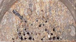
Figure 1 shows an uncoated tubesheet and tubes after one year in cooling water service.
Figure 1. After one year in service, this tubesheet exhibits severe fouling.
In contrast, Figure 2, shows a coated tubesheet and tubes after one year in the same service being supplied by a common header.
Generally, tube pitting is corrected in one of three ways:
Cleaning. Because of the bacterial component of pitting, removal of tube deposits and adoption of better methods for tube cleaning can halt deterioration or at least stabilize the rate. Deep pits can be identified through eddy testing and then plugged prior to cleaning. Rough cleaning can be accomplished by brushes and scrapers or by using hydrolyzing or sponge balls. Tubes need to be decontaminated as well. Low-chloride potable water that has been demineralized or water conditioned with a chloride neutralizer can flush out contaminating chlorides. Finally, abrasive blasting should be employed to remove the last vestiges of contamination in the tubing.
Figure 2. After similar period, coated tubesheet shows minimal fouling.
Chemical treatment. Biocides or oxidizing agents can be used on the tubes to control biological activity. After a biocide treatment, application of biostats, a milder form of chemical control, can control future growth. In recent years, chemical treatment has fallen out of favor due to the toxic nature of the substances used.
Retubing. If severe pitting can’t be alleviated, it may be necessary to resort to complete retubing of the heat exchanger, particularly in older equipment that has run for years. Choosing a more appropriate tube material or accelerating maintenance can stave off recurring fouling and corrosive conditions; however, retubing is extremely costly and may have to be done several times to prolong the working life of the apparatus. The bare tube surfaces will inevitably sustain pitting and bacterial build-up as long as they remain uncoated.
None of these options is as viable or cost-effective as coatings.
What about heat transfer?
Decades of service history and studies have proven that coatings can significantly improve heat transfer and overall performance. While the thermal conductivity of the coating alone is less than that of the metallic parent tube, this is offset by several factors.
The first is normal design margin. Generally, heat exchangers are designed with a fouling factor of 0.001 or 0.002 ft2°F/Btu. Adding a coating to the tube ID impacts the thermal duty by only a factor of 0.0006 – 0.0008 ft2°F/Btu the same at fully dry film thickness. Moreover, the coating can either totally eliminate the subsequent fouling or greatly reduce the accumulation of typical micro- or macro-fouling, thus enabling greater heat transfer.
The second major factor is boundary-layer drag reduction. About 70% of the total heat-transfer resistance of an exchanger is a result of boundary layer drag. Tube wall friction due to fouling reduces designed flow and creates an insulating barrier of low velocity fluid. Polymer coatings cut the friction at the tube wall by a factor of 40 compared to bare metal. Less friction decreases the boundary layer drag and substantially opens up the flow profile.
Data from two refineries showed flow rate improvements of 80% and 100%, respectively, in coated tubes compared to new “bare” tubes in the same fluid train. This increase in flow and the low surface energy of the coating contributes to the improved overall thermal efficiency of the heat exchanger.
Coated tubes have maintained 100% of their heat transfer efficiency over years of service without cleaning cycles. One five-year study that took monthly data on water- and process-side temperature differentials showed that coated heat exchangers remained at optimal thermal duty over that period while bare tubes saw performance drop by more than 50%.
An economical proposition
The cost of coatings is easily only one-quarter that of retubing. Once the tubes are recoated after their first 10-year period, they remain functional in perpetuity, requiring minimal maintenance for the rest of the life of the heat exchanger. Over 12-years, the savings from coating the tubes in a single large heat exchanger could exceed $8 million.
At one refinery, six heat exchangers in a catalytic cracker recovery unit’s refrigeration section required maintenance. They weren’t operating efficiently; examination showed severe tube corrosion and pitting. Two of the six exchangers needed complete retubings due to age and damage over time. The four remaining exchangers had only been operating for three years but still had telltale wear and tear, corrosion and pitting.
Refinery management opted to apply coatings to all six exchangers to prevent further damage and to decrease fouling from sulfate-reducing bacteria. By coating all the equipment, ongoing preventive maintenance would suffice to reduce stoppages, repairs, replacements and the need for any retubings — and the unit would see better performance from the equipment in the refrigeration section.
After retubing and coating, the coolant fluid pressure in the two older heat exchangers dropped 10% from its previous 230 psi to within a steady range of 190 to 200 psi. The additional cooling eliminated all gas recycling and kept the unit at a 96% recovery rate, even in the hottest summer months, which amounts to an extra 1,000-bbl/d output. In contrast, the regular and long-duration cleaning cycles previously required caused lost production of 10,000 bbl/d. During their first three years of “bare” pipe service, the four younger exchangers experienced an increase in pressure drop of 15 psi per year. Once the tubes were coated, the pressure performance stabilized.
The refinery expects a 10-year minimum coating life for the exchangers, given some minor tubesheet touchups during maintenance periods. After a decade, the tube bundles may need to be grit-blasted and possibly recoated, but the life expectancy of the heat transfer equipment is conservatively expected to exceed 20 years and the maintenance required is minimal compared to the bare pipe alternative.
The bottom line
The methodology of tube coating is well proven and many of the world’s largest companies rely on it. There are now more approaches to produce the desired outcomes and reduce the losses incurred through inefficient heat transfer. The best way to start is to consider the various conditions and identify the most efficient method to clean and coat the tubular systems.
By taking care of the small details — paying attention to your tubes — you can eliminate unnecessary maintenance, cut energy costs and enhance operational efficiency over the lifetime of your heat transfer equipment.
Making the most of coatings
The inherent passivation of nickel and chrome/moly alloy materials in cooling water provides significant advantages in corrosion resistance. However, carbon steel often is chosen for exchanger tubing because it’s the least expensive material available, only about a quarter of the cost of materials like admiralty brass, 70/30 or duplex stainless steel.
Maintaining optimal performance of carbon steel tubes demands careful attention to cooling water flow rates, pH levels and temperatures throughout a unit that may have many pieces of equipment tied to the same loop. Not surprisingly, aggressive fouling and corrosion often impact operations. So, plants frequently consider an alloy upgrade for exchangers. However, tube ID coating offers a lower cost alternative.
Polymer linings such as high baked phenolics, phenol epoxy and novolacs epoxy are commonly used in “product” environments like tankage, transport containers and vessels. At such ambient temperature conditions, these linings resist a wide range inorganic and organic acids, solvents and hydrocarbons. Typical applications call for coating films to be applied at greater than 20 mils, and materials often are loaded with glass or ceramic pigments to inhibit porosity over time.
However, heat exchangers are a tougher application; their operating temperature and pressure must be taken into account in choosing coatings. The limits of high performance epoxy coatings in immersion service (with neutral pH water) are about 300°F and about 400°F in “dry” service.
A lining material for thin-film applications suitable for cooling water service must provide the following characteristics:
- homogeneous coverage at films less than 12 mils thick;
- adhesion resistance exceeding 2,500 psi;
- ability to withstand thermal cycling and occasional excursions beyond normal operating temperatures; and
- superior release of foulants such as calcium and sulfite deposits.
Heat-curing — up to 400°F for baked phenolics and 250°F for epoxies — can improve the chemical- and heat resistance properties of these linings.
While the tubeside of exchangers in cooling water service typically has operating temperatures well within the limits of the coating, also always consider product-side temperature conditions and flow rates. Plant maintenance “steam out” will impact coating integrity if temperatures exceed out-of-service or dry tubeside coating limits.
Widely used ¾-in. and 1-in. outer-diameter tubing sizes are amenable to coating; the general limits of coating and full inspection of tube insides is about 0.40-in. ID. Tubes up to 60 ft. long have been fully coated using a airless spray technique; “U” tube and hairpin design exchangers can be coated.
Have all coated surfaces inspected for discontinuities or “holidays.” NACE has a procedure for a low-voltage spark test for thin film (<20 mils) coatings. This procedure uses a “fish tape” to wipe a wet sponge through each exchanger tube, a “beep” signals a holiday, which the applicator should repair and recheck using the same procedure.
Ed Curran is president of Curran International, Dickinson, Texas. E-mail him at [email protected].


