Effective troubleshooting requires an understanding of the basics of how systems work. One fundamental for flow systems is that parallel paths connecting two points must have the same pressure drop. This is an extremely powerful tool for analyzing utility systems such as cooling water, plant air, fuel gas and nitrogen. It also helps in understanding many process systems.
[pullquote]
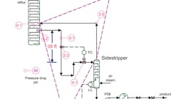
The rule holds true even when the fluids move in different directions in the paths, as illustrated in Figure 1. It shows a system that has two parallel flow paths between a main tower and a sidestripper. In one, liquid goes from the main tower to the sidestripper, while in the other, vapor returns from the sidestripper to the main tower; the flow paths are parallel but in opposite directions.
Figure 1. Two parallel flow paths exist: one for liquid from the tower, the other for vapor from the sidestripper.
That system had a flow capacity constraint. Even with the control valve fully open, the product flow rate was too low. So, we had to determine whether the system had reached its limit or something needed fixing.
To get vapor to return to the main column, the sidestripper must have a higher operating pressure than the main column. Figure 1 shows the pressure drop through each component in both flow paths — using as common endpoints the vapor return nozzle location on the tower and the vapor space above the top tray in the sidestripper. Other locations could serve as the common endpoints for the paths; it’s wise to pick ones that make the calculation straightforward.
Table 1 summarizes the pressure balance for Path 1 versus Path 2. It lists the pressure drops as negative numbers for Path 1 and positive numbers for Path 2. This is because the flow along Path 2 is in the opposite direction of that of Path 1. As long as the calculation keeps track of signs, any consistent basis works.
Table 1. Flows in parallel paths are in different directions, so pressure changes have different signs.
We measured the pressure at the sidestripper vapor space and the pressure drops across the control valve and orifice plate. We calculated values for the other components.
The sidestripper inlet is 38-ft lower than the liquid draw nozzle. At a density of 40.6 lb/ft3, this elevation change yields a pressure rise of 10.7 psi.
The pressure drop difference between the two paths is 0.4 psi. This equals ~1.4 ft of fluid at operating conditions. Comparing the potential error in pressure drop (1.4 ft) to the total height available (38 ft) gives closure to within 4%. So, considering the accuracy of the measurements and calculations, the system is working as expected. From a straightforward maintenance approach, nothing is broken or plugged.
Therefore, getting more flow from the system requires:
• reducing the pressure drops in the liquid line to the sidestripper; or
• lowering the pressure drop in the vapor return line to the main tower.
The simplest step to decrease pressure drop is to open any bypasses around the liquid flow valve (see: “Open Up More Capacity”). This may not be acceptable in a specific plant. If a control-valve bypass exists, the next step would be to replace the control valve with one that allows more flow. The third step would be to add a parallel vapor line with a hot tap. Other modifications would require a unit shutdown.
Keep simple rules in mind when troubleshooting flow systems. Flows through parallel paths — even if in opposite directions — must give the same pressure drop through each path.


