The chemical processing industry certainly doesn’t lack challenges today. Rapidly escalating capital costs and high energy prices are the new reality.
Many studies indicate that separations consume 50% to 70% of the capital and energy of a traditional chemical process [1]; so, seeking improvements in this area clearly should receive a high priority. One of the more effective methods of reducing both the capital and energy costs of separations units is installation of dividing wall columns (DWC) where appropriate. While results, of course, vary, a DWC typically can cut capital and energy costs by approximately 30% compared to a traditional two-column system.
The idea of the DWC isn’t new. The original patents on the concept were granted to Wright of Standard Oil in 1949 [2] — and that patent cited prior art! Today there’s a large body of literature on the DWC and associated concepts — a recent survey of patents and published articles revealed roughly 400 relevant matches. Schultz et al. [3] relatively recently authored an excellent overview article. Since that article, other announcements and presentations have indicated a gathering momentum in distillation intensification. For instance, in 2005 at the 7th World Congress of Chemical Engineering, BASF, a leader in DWC implementation, reported more than 40 DWC in commercial service. In a 2006 symposium [4], ExxonMobil announced the successful revamp of a 380-cm/430-cm-diameter tower that removes xylene from reformate. Dow has operated an experimental DWC facility in Midland, Mich., for about eight years. During the same time, numerical expertise for the modeling of DWC systems has been developed — and bolstered and validated by the experimental units.
Figure 1. Conventional scheme -- When two
towers are used to provide three pure
products, energy is lost separating the
middle component, B.
Click on image to download a full-size PDF.
The Fundamentals
Let’s consider the separation of three components, A, B and C, with A being the lightest, C the heaviest, and B the intermediate volatility component. One option is to use a direct sequence, removing A first with B and C going out the bottom. Figure 1 shows this sequence, along with the relative tower concentration profiles for B.
In the first column, the concentration of B reaches a maximum somewhere in that tower but necessarily must be lower in the bottoms. This represents a thermodynamic loss that’s unavoidable in the sequential distillation scheme.
Now, consider an alternative two-column arrangement for the separations where in the first tower, rather than performing the sharp separation between component A and B, we pre-fractionate the components (Figure 2). In the first column, we take the entire amount of A and some fraction of B out of the top of the tower. The remaining fraction of B and the entire amount of the C exits the bottom of the tower.
Figure 2. Alternative arrangement -- In this
two-column variant, the first column serves
as a prefractionator instead of producing
pure product.
Click on image to download a full-size PDF.
Figure 2 shows the towers arranged with individual reboilers and condensers but this isn’t required and alternative arrangements may be developed. If we thermally integrate the two towers by using a single reboiler and condenser, we arrive at an arrangement (Figure 3) often referred to as a “fully thermally coupled” or “Petlyuk” column, after the noted Russian academician who wrote extensively on the thermodynamics of separating multi-component mixtures. The logical next and last step on the way to the DWC is moving the prefractionator inside the second tower so the prefractionator and the main column are a single vessel (Figure 4).
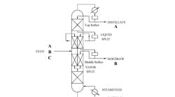
Figure 5 illustrates operation of a DWC unit. A packed column is used for ease of illustration, as is the symmetry of the sections, which isn’t a design requirement. The feed enters on the prefractionator side of the tower. If the separation is to be sharp, then the entire amount of A and some fraction of B will go over the wall and up the column to the upper rectification section. The entire amount of C and the remaining portion of B will go under the wall to the lower stripping section. The location of the partition determines the ratio of vapor entering the two sides of the dividing wall section.
Figure 3. Integrated columns -- Fully thermally
coupled Petlyuk arrangement needs only a single
reboiler and single condenser.
Click on image to download a full-size PDF.
Our discussion thus far has been about “sharp separations,” that is, ones where a stream, be it overhead, middle or bottom, largely consists of a single component — that’s where our experience lies. However, a DWC also can bring value to “non-sharp” applications, i.e., those with intermediate components between A and B or B and C; these components will distribute according to the vapor/liquid equilibrium that governs the separation.
To sum up the basics:
• A DWC is a distillation column that has a vertical partition wall in the central section.
• The column may contain either trays or packing. While it may be easier to visualize a DWC with packing, there’re examples of successful installations of both types. (The ExxonMobil application previously cited is a tray tower.)
• The feed side of the two compartments acts as the prefractionator and the product side as the main column.
• In the case of a sharp split, a DWC can be used to produce three pure products from a single tower.
• A DWC can handle more than three components. There may be components lighter than the light component A that’s in the overhead product, and components heavier than the heavy component C that’s in the bottom product.
Figure 4. Single shell -- The thermally coupled
Petlyuk approach also can be configured within
one vessel.
Click on image to download a full-size PDF.
Appropriate Applications
We’ll give some general heuristics for when DWC installations should (and shouldn’t) be considered. However, different companies view capital, energy and risk differently and, thus, evaluate a project according to disparate sets of metrics; so, one firm might support an installation while another might not.
With that caveat, here’re some broad guidelines:
• Consider a DWC when the middle or B component is at least 20% of the total stream flow. Although it’s possible to utilize a DWC at values below this, there may be better methods of arranging the separation.
• Don’t use a DWC if the pressure difference between the conventional sequence is high. A DWC operates as a single tower, so it runs at a single pressure. If the condenser temperature is selected to fit the available utility, then the reboiler temperature is, by definition, set by the pressure drop and the composition of the bottom stream. This may mean that a higher level of heating medium or a lower level of condensing medium is required to meet restrictions on the top or bottom temperature.
• Carefully evaluate energy use — this is an important point. It’s been shown that the fully integrated arrangement or the DWC consumes the lowest energy, but that doesn’t account for the level of energy being used.
Figure 5. Dividing wall column -- This
energy-efficient scheme features a vertical
partition wall in the central section.
Click on image to download a full-size PDF.
Because a DWC operates as a single unit and at a single pressure, the reboiler must run at a temperature consistent with relatively pure C. In an analogous way, the condenser must run at a temperature consistent with the lightest component. Looking at Figure 2, it’s obvious that this arrangement could be configured to use a lower level of heating medium on the first pre-fractionation tower. Thus, it may be that a DWC is better from a First Law perspective but not from a Second Law perspective. DWC applications are selected because of the potential to reduce capital and energy.
Piloting
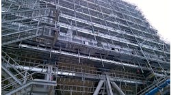
For the development of new DWC applications, Dow has designed and built the Midland pilot plant (Figure 6) so that it has the same configuration as a commercial unit and closely mimics industrial operations. This setup is used to demonstrate the process concept and purification capability for a particular separation. It also generates experimental data to test the validity of both steady-state and dynamic numerical simulations of DWC applications of particular interest to Dow. In addition, the pilot plant is utilized to assess proposed control schemes and to help shorten or eliminate the learning curve in the start-up and operation of commercial DWC units. This is particularly important when numerical simulations indicate potential operational challenges. For example, when feed concentrations can vary over time or when feed conditions are such that flashing can occur inside the column, experimental information is helpful in the design of control strategies.
Figure 6. Pilot plant --
This unit enables
evaluation of potential
applications and
control schemes, and
helps ease startup of
commercial DWC columns.
The DWC pilot plant is fully automated; more than 20 control loops are manipulated and monitored by a data acquisition and control system. As partners consider a DWC installation, a key to building confidence in the proposed installation is viewing the experimental unit on robust closed-loop control. The DWC features more thermocouples than found in full-scale applications. These thermocouples are located along the entire length of the DWC to allow for easy selection of the most responsive temperature (MRT) control locations for different applications.
The experimental unit DWC uses random packing. The vertical partition is located in the middle of the column, giving rise to a 1:1 ratio for the vapor split between the feed (pre-fractionation) and the product (side-draw) sides. The liquid split ratio is determined via a numerical simulation of the application to allow the DWC to meet quality specifications of all three products and optimize the distribution of the middle-boiling component between the top and the bottom of the prefractionator to minimize energy (reboiler duty) requirements. To facilitate distribution of liquid reflux to the two sides, liquid leaving the rectification section is collected using a total liquid collector and drawn off to an accumulator. The liquid then is pumped back to the two dividing-wall compartments through two Coriolis mass flow meters to achieve precise control of the liquid split ratio. Typically, this ratio is kept constant in the operation and is adjusted only slightly to ensure product quality requirements are met. The top reflux/distillate streams and middle reflux/side-draw streams are processed in a similar manner.
Effective Control
Simultaneously maintaining the product specifications on three products may appear to be a daunting task considering the efforts undertaken for composition control of a conventional distillation column with two products. The fundamental tenets of providing sufficient energy to separate the key components and maintain the material balance split apply to the DWC.
Reflux drum level is controlled either by the reflux flow rate (L) or distillate flow rate (D), depending on the reflux ratio. With high reflux ratios (L/D>5), the reflux flow is used. Similarly, where the middle product is withdrawn from the column, the accumulator level is controlled by either the middle product or the middle reflux flow rate. At the bottom of the column, either the bottoms flow rate or reboiler duty are suitable for controlling the sump level.
Product compositions are maintained by treating the DWC, in effect, as the equivalent of three distillation columns — with the pre-fractionation (feed side of the wall) section separating A from C, the top half of the column separating A and B, and the bottom half separating B and C. The reboiler supplies the energy to separate the components. The bottoms product specification is maintained by adjusting the reboiler duty or the bottoms flow rate, depending on which stream is controlling reboiler level. Dow’s typical implementation utilizes the reboiler duty to control the separation of B and C.
To maintain the material balance split between B and C, we control the MRT, because it’s the temperature most sensitive to composition changes within the column. Typically this occurs when the vapor space is 50% B (or 50% C). Adjusting the middle reflux rate (when the side-draw flow rate controls the middle product accumulator level) or the middle product draw rate (when the middle reflux controls the middle product accumulator level) changes the temperature of the column by regulating the inventory of B in the column, facilitating control of the separation. We adjust the MRT setpoint to maintain the middle product composition. Analogously, the separation between A and B has a MRT. By adjusting the reflux rate or distillate rate, the inventory of A in the column can increase or decrease, changing the composition in the column. Monitoring the composition of the A product provides feedback on changing the upper MRT setpoint.
The last element of control is obtaining the split between A and C on the pre-fractionation section of the column (feed side of the wall). During DWC design, simulation determines the split of reflux to each side of the wall. During operation, this split is maintained by having one stream control the accumulator level. A ratio controller adjusts the other stream’s flow rate to maintain the liquid split ratio. Dow has successfully operated several pilot-scale DWC projects using this control philosophy.
John G. Pendergast is a Freeport, Texas,-based scientist, senior technical leader in the Engineering and Process Sciences group of The Dow Chemical Co., David Vickery is a senior process engineering associate at Dow’s Engineering Solutions Technology Center in Midland, Mich., Patrick Au-Yeung is a senior research specialist in the Engineering and Process Sciences group in Midland, and Joe Anderson is a senior research specialist at Dow’s Michigan Operations, Midland. E-mail them at [email protected], [email protected], [email protected], and [email protected].
References
1. Adler, S., Beaver, E., Bryan, P., Robinson, S. and J. Watson, Vision 2020: 2000 Separations Roadmap, Center for Waste Reduction Technologies, American Institute of Chemical Engineers, New York City (2000).
2. Wright, R. O., “Fractionation Apparatus,” U. S. Patent 2,471,134 (May 24, 1949).
3. Schultz, M. A., Stewart, D. G., Harris, J. M., Rosenblum, S. P., Shakur, M. S. and D. E. O’Brien, “Reduce Costs with Dividing Wall Columns,” p. 64, CEP (May 2002).
4. Slade, B., Stober, B. and D. Simpson, “Dividing Wall Column Revamp Optimizes Mixed Xylenes Production,” IChemE Symp. Series, No. 152, Institution of Chemical Engineers, Rugby, U.K. (2006).
5. Becker, H., Godorr, S., Kreis, H. and J. Vaughan, “Partitioned Distillation Columns — Why, When & How,” Chem. Eng., p. 68 (Jan. 2001).
6. Mizsey, P., Hau, N. T., Benko, N., Kalmar, I. and Z. Fonyo, “Process Control for Energy Integrated Distillation Schemes,” Computers & Chem. Eng., Vol. 22, p. S427 (1998).
7. Triantafyllou, C. and R. Smith, “The Design and Optimisation of Fully Thermally Coupled Distillation Columns,” Trans. IChemE, Vol. 70, Part A, p. 118 (March 1992).
8. Annakou, O. and P. Mizsey “Rigorous Comparative Study of Energy-Integrated Distillation Schemes,” Ind. Eng. Chem. Res., Vol. 35, No. 6, p. 1,877 (1996).
9. Agrawal, R. and Z. T. Fidkowski, “Are Thermally Coupled Distillation Columns Always Thermodynamically More Efficient for Ternary Distillations?,” Ind. Eng. Chem. Res., Vol. 37, No. 8, p. 3,444 (1998).
10. Serra, M., Espuna, A. and L. Puigjaner, “Control and Optimization of the Divided Wall Column,” Chem. Eng. and Process., Vol. 38, p. 549 (1999).
11. Petlyuk, F. B., Platonov, V. M. and D. M. Slavinskii, “Thermodynamically Optimal Method for Separating Multicomponent Mixtures,” Intl. Chem. Eng., Vol. 5, No. 3, p. 555 (1965).


