Question from February's Chemical Processing
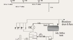
During a routine walkthrough at a new job, we found a problem with how the relief valves are laid out for a distillation column (Figure 1). After further thought, we wondered if the piping was undersized. A review of the relief scenario and a mechanical sketch of the piping revealed some background. The relief valves are sized for a total flow of 170,000 lb/hr for fire and other scenarios; fire isnt the worst. All valves are conventional, not pilot valves or balanced bellows. Sizing was performed for a mixture in the column of 64% ethanol and 36% ethyl acetate. The relief conditions were: 150 psig and 149°C.
There are other problems with the set-up, which need to go to the maintenance manager right away. What should go in the report? What must be done to improve the safety of the relief system?
Check out the drawings first
I am intrigued by your Process Puzzler in part because there isnt enough information to complete it. Although missing data is pretty much par for the course, you implied that this was just walkthrough on the job. Apparently we need to take better notes.
Heres what I see that needs to be confirmed in a follow-up inspection:
- The reflux drum has a relief that discharges to the same 20-in. header as the relief valves on the distillation column. Using the same header could have some impact on the capacity of the line since fire isnt the worst case.
- The line sizes to the relief inlets are apparently making changes as the line progresses to the various relief valves. Our site convention would be to show every step change from the 12-in. main line at the tees to the relief valves. I know that some sites assume that the tee represents the line size changes.
- This leads me to assume that the tees to the 4x6 P orifice reliefs are 6-in. lines since there are 4x6 reducers at the relief inlets.
- However, the last relief in the line (the 3x4) has a 3x8 reducer in front of it that implies the header is an 8-in. line.
- This brings us to the discharge piping. Could you please confirm if there are changes along the way from the 4in. discharge to the 20in. main header and where they occur? [Is there an answer to his question?]
Ben Thayer, independent consultant
Grand Rapids, Mich.
A similar situation
To read this in-depth response, please click here.
Fredrick I. Rippee, chief engineer
Fred Rippee Engineering, Hillsboro, Ore.
Change the vent pipe and PSV settings
In provided Case Study, three Pressure Relief Valve (PRV) are provided on the top of distillation column. Two (P orifice) are set at 158 psig and one (K orifice) is set at 150 psig. Assumed that Blowdown drum is of sufficient capacity and bypass valve to PRV battery is for start up operation.
If we ignore the flow capacity of PRV, in case of pressurization at slightly more than 150 psig pressure K orifice will release the pressure. So, in any case pressure will never reach to 158 psig. So, during the fire also it may / may not operate. Ultimately, all vapor flow will choose less resistance path that is K orifice.
Now, calculating the designed volume of vapor (as per Ideal Gas law) at 20,000 lbs/hr passing through K orifice, volume of vapor will be approx. 16,995 ft3/h and velocity through 4 in. pipe will be 54 ft/s, which is very high. Due to high velocity and reduced pressure on down stream of PRV, it can get condensed inside pipe which will also create resistance for the vapor flow.
To prevent the above said problem following two can be done: 1) Increase down stream line size of K orifice to 6 in. with 4x6 reducer;2) Set the two PSVs with P orifices at 150 psig instead of 158 psig; and 3) A Rupture disk with sufficient suitable size parallel to PRV battery can be placed as an additional safety feature.
Nishant Patel, process engineer
Larsen and Toubro, Ltd., Vadodara, India
Consider maintenance issues
Looking at the diagram from a maintenance point of view: shouldnt all of the relief valves have an individual isolation block valve that is Car Sealed Open (CSO)? Since this is a continuous process, block valves should be installed under each pressure relief valve.
Keith Parkey, I&E designer
Lyondell, Houston, Texas
Correct some costly mistakes
There are numerous mistakes in this grandfathered system that need attention. When this relief system was designed it was probably in compliance. Given that the worst case scenario often involves two-phase flow, the vent, inlet and headers are probably too small. Here's a summary of mechanical problems with this relief system in order of priority:
- The 12-in. relief header connects to the condenser feed line instead of directly to the vessel it's protecting.
- The 3x4-in. PSV will relieve first creating backpressure on the two larger valves inhibiting their action.
- Although it's hard to be precise without a calculation, the blowdown drum seems to be too far away (400 ft) to prevent backpressure acting on all the valves.
- The PSV on the reflux drum isnt independent, especially in case of fire; the header design must carefully account for this addition.
- No vacuum breakers are shown anywhere in the condensing train or column.
- Two block valves should be installed (CSO) to permit maintenance access to the PSVs.
- Unless the 4-in. maintenance valve is easily accessible to operators it should be automated (ASME Code doesnt recognize this valve as meeting relief code.).
Another observation is the pipe layout is poor. Using nozzles and flanges in place of concentric reducers creates high pressure drops and unpredictable flow conditions. In addition, if a branch tee in a compressed air system cost 10 psi what is the cost for critical flow inside a relief vent? (see "Energy savings are often opportunities disguised as problems," CP, Aug. 2006, p. 26) Why not design wyes instead of elbows and tees?
Dirk Willard
senior editor
June's Puzzler
A contractor has been asked to increase the plant capacity of an existing helical-coil vaporizer. The furnace already has an economizer. The results are disastrous the plant maximum rate has been reduced by more than 10%. The vaporizer is running so hard the fins of the economizer are starting to burn off. The flame is too long (Figure 2). What can we do to eliminate this dangerous problem and increase the vaporizer rate while accounting for NOx limitations? Although the space between the coils is adequate, there is some concern about the coil skin temperature if we change the flame. What are your thoughts?
Figure 2. The flame length is too long, forcing us to reduce the feed rate to the vaporizer.
Send us your comments, suggestions or solutions for this question by May 4, 2007. Well include as many of them as possible in the June 2007 issue and all on CP.com. Send visuals a sketch is fine. E-mail us at [email protected] or mail to ProcessPuzzler, Chemical Processing, 555 W. Pierce Rd., Suite 301, Itasca, IL 60143. Fax: (630) 467-1120. Please include your name, title, location and company affiliation in the response.
And, of course, if you have a process problem youd like to pose to our readers, send it along and well be pleased to consider it for publication.

