Phase changes in the downstream processing or handling of solids cause many process problems. These changes can alter the form of the final product or mandate rework of a material. Too often, though, phase changes do not get adequate attention.
Consider these classic problems:
• The particle size of a batch product suddenly changes.
• The filtration time of a slurry alters over time or the cloth blinds unexpectedly.
• A dried product clumps even though the processing conditions in the dryer didn’t vary.
• An evaporator begins to foul unexpectedly.
Many factors can cause these situations, but phase change usually is not the first thing that comes to mind. However, if you are processing an organic, phase change should be one of the first considerations even when your research people say there is only one phase for the material. Polymorphs and solvates in organic and inorganic chemicals can exist briefly enough to dramatically change the outcome of a crystallization process.
My personal experience indicates that about one-third of all crystallization problems stem from polymorphs or solvates. These often are overlooked in the development of a product, which is not surprising given the extreme pressure to get to market. Also, operating conditions can change for an existing product as plants strive to become more efficient. For example, switching to a different, maybe larger, reactor without considering the difference in mixing or reactant addition can play havoc with the process. Even the most sophisticated process-modeling programs don’t take some of the micro-fluidic and reaction effects into account, especially reactor size changes and piping layout. Phase changes frequently are ignored if they don’t show up in the reactor and solid/liquid separator as a design issue.
One very common complaint is about erratic filtration rates, especially in an existing process. After all, in most cases the purpose of the crystallizer is to make solid/liquid separation efficient, not just to give a larger-sized product. The problem can be a drop-off in rate of filtration, pluggage of the filter or variation in the amount of time needed for a batch.
The two examples that follow highlight on how phase change can affect a process
More than a shipping change
A plant had been crystallizing a material and sending the batch to centrifuges to make a wet cake. The cake then went to another location for further processing. As the scale of operations increased, the plant decided to ship the wet cake by railcar. To accommodate this, the slurry from the crystallizer was pumped to a feed tank for the centrifuges, which were located next to the railcar loading station. As you can imagine, the line had to be fairly long and the velocity high to prevent sedimentation. Almost every batch had a decline in the filtration rate. In some cases only half of the contents of the feed tank could be processed. The remainder was either disposed of or reworked. The cloth and the centrifuge manufacturer both were blamed and a wide variety of measures were taken to try to solve the problem.
The plant discovered that by pumping only half of the contents and then refilling the tank from a crystallizer almost all of the slurry could be processed — but at too slow a rate. Average crystal size was not changing but the particle size distribution (PSD) was wider than before the change to the railcar loading system. In this case three factors contributed to the problem:
1. Although the finer crystals were distributed uniformly in the crystallizer, more of the larger crystals were accumulating near the bottom of the vessel, especially just before pump-out of the crystallizer.
2. The pump was located closer to the railcar loading station, which put a lower net positive suction head (NPSH) on the inlet when the flow rate was increased. Also, due to the long distance, the pressure rise across the pump was heating the slurry.
3. The feed tank used a dip leg to avoid splashing in the tank.
While each of these issues normally would not cause a problem, the three together created a poor filtration rate.
Pump-out of the crystallizer allowed the larger crystals to get to the feed tank early in the process. During the last portion of the pump-out, the pump was handling slurry with very fine crystals and a lower solids’ content. Localized heating resulted in both dissolution of some of the fines and a supersaturated solution in the tank. Larger crystals grew slightly because the dip leg put the solution into the bottom of the tank but some secondary nucleation was occurring. Even though the tank’s impeller provided some recirculation, the larger crystals still collected in the lower portion of the tank.
By removing only half of the tank’s contents before refilling from a crystallizer, the operators discovered that coarser particles could be replenished to provide better filtration rates. However, in the long run the finer crystals would accumulate and eventually blind the centrifuge.
The operators thought that running the impeller when the centrifuge was not being fed would provide adequate recirculation within the tank. However, the impeller could only keep the solids off the bottom of the tank and most of the mixing was caused by the recycle of slurry.
To verify this scenario, PSDs were examined before and after the pump and during the crystallizer pump-out. As expected, the PSD did change as the crystallizer was emptied, with a higher slurry density and larger average particle size at the beginning of the cycle. In addition, finer crystals were “disappearing” after the pump throughout the entire transfer. A close look at the impeller of the pump showed slight signs of cavitation, which meant some of the solvent may have been evaporating.
Two equipment changes and one process change were made based on the PSD studies. The transfer pump was relocated closer to the crystallizer and the impeller in the feed tank was switched to an axial flow design. The feed pump was adjusted so that there is always flow to the feed tank, even during filtration cycles.
Impact of polymorphs
A very similar crystallization situation occurred at another plant. There, a large variation in filtration rate occurred, but it was never repeatable. Occasionally, the plant would get a “super” batch that filtered in half the normal time. This was a very desirable, but seemingly random outcome. That batch had a slightly larger and narrower PSD.
Examination of the particles under a microscope revealed that the habit was different. No polymorphs or solvates were known for this material — however, an evaluation of the chemical structure suggested at least four polymorphs and two solvates.
This led to a closer look at process conditions. The standard operating procedure called for cooling of the under-saturated solution until a heat flux was observed in the jacket of the vessel. The difference between the inlet temperature and the outlet temperature was used to mark this heat flux. The temperature was held constant for a fixed period of time and then the batch cooled to the final temperature at a constant rate. In the super batch case, this step-change in heat flux was not observed; cooling occurred below the normal holding temperature at which the heat flux usually was seen. There was no holding period and cooling continued to the final temperature.
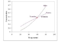
What was really happening in the process got lost in translating the research work to the process development and operation. This material exhibited classic enantiotropic behavior: a transition temperature between two polymorphs (alpha and gamma) as shown in Figure 1. The gamma form is unstable and has lower solubility above the transition temperature while the alpha form has the lower solubility below the transition temperature.
Don’t be fazed
In both of these cases, a key indicator of a phase change issue was the dramatic shift in the ease of filtration. It is important to identify polymorphs and solvates for a product and to determine any critical temperature early in process development and design (see sidebar). Also, watch out for minor changes in the processing layout. Understand what you are measuring and why. In these examples finding the potential cause of the problem was a fairly short and easy process once the fundamentals were examined. Verifying it was much more difficult. However, in most production environments we don’t need a definitive study but can alter the processing conditions to test the causes. Then a more cost-effective solution often can be developed and implemented.
|
1. Vital experiments to conduct for scale-up and design 2. Tools and data to use to evaluate phase or solvate change 3. Ways to minimize production problems |


